Transcription of OP-AMP Filter Examples - Astronomy
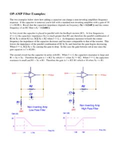
1 OP-AMP Filter Examples : The two Examples below show how adding a capacitor can change a non-inverting amplifiers frequency response. If the capacitor is removed you're left with a standard non-inverting amplifier with a gain of 10. (1 + R2/R1). Recall that the capacitors impedance depends on frequency (Xc = 1/(2 fC)) and the corner frequency of an RC Filter is fc = 1/(2 RC). In first circuit the capacitor is placed in parallel with the feedback resistor (R2). At low frequencies (f << fc) the capacitors impedance (Xc) is much greater than R2 and therefore the parallel combination of R2 & Xc is about R2 ( R2|| Xc = R2 when f << fc ).
2 As frequency increases towards the corner frequency the impedance of the capacitor decreases and becomes comparable to that of the resistor. This lowers the impedance of the parallel combination of R2 & Xc and therefore the gain begins decreasing. When f >> fc, R2|| Xc = Xc causing the gain to drop. In this case the gain bottoms out at one since the gain equation is 1 + R2/R1. The second circuit has the capacitor in series with R1. When f << fc the capacitors reactance is large and R1 + Xc = Xc. Therefore the gain is 1 + R2/ Xc which = 1 when Xc >> R2.
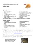
3 When f >> fc the capacitors reactance is small and R1 + Xc = R1. Therefore the gain is 1 + R2/ R1 which = 10 when Xc << R1. Vin Vin Vout Vout R2 R2. 9K 9K. C1. C2 R1. R1 1K. 1K. Non-Inverting Amp Non-Inverting Amp GND. High Pass Filter GND. Low Pass Filter Gain (db) Gain (db). 20 20. 0 0. Freq (Hz) Freq (Hz). 177 16K. High and low pass filters can be made by adding capacitors to inverting amplifiers as well. The first circuit is a low pass Filter . At low frequencies the capacitors impedance is high, much higher than R2, and therefore doesn't affect the circuit (XC||R2 = R2).
4 At high frequencies the capacitors impedance is low, much lower than R2, and therefore limits the impedance of the parallel combination (XC||R2 = XC). Since the gain equation for a non-inverting amp is R2/R1 the gain doesn't bottom out at one. The gain continues to decrease as frequency increases beyond the cutoff frequency. The second circuit is a high pass Filter . At low frequencies (below the cutoff frequency) the capacitors impedance is high, much higher than R1, and therefore R1 + XC = XC. The gain is therefore R2/XC.
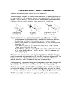
5 At high frequencies the capacitors impedance is low, much lower than R1, and therefore R1 + XC = R1. The gain is therefore R2/R1. C2. R2 R2. 10K 10K. R1 C1 R1.. Vin Vin 1K Vout 1K Vout GND GND. Inverting Amp Gain (db). Gain (db) High Pass Filter Inverting Amp 20 Low Pass Filter 20. 0 Freq (Hz). 0 Freq (Hz) 160 160 The low pass and high pass Filter can be combined into a band pass Filter . In the Examples below the corner frequencies were chosen to be the audio band (20Hz 20 KHz). Notice the difference in the gain outside of the pass band.
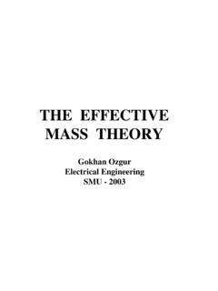
6 The gain of the inverting amplifier continues to drop as you get farther away from the pass band. The gain of the non-inverting amplifier only drops to 1 (0db). C2. Vin Vout 80pF. Inverting Amp R2. Band Pass Filter R2. 100K. 9K. C1 R1 C2.. Vin 10K Vout C1. 8uF. GND Non-Inverting Amp R1. 1K Band Pass Filter Gain (db) GND. Gain of 10 in audio band Gain (db). 20 20. Freq (Hz). 0. 0. 2 20 20K 200K 2 20 20K 200K Freq (Hz). Gain of 10 in audio band Each gain stage can be combined with another for a larger gain and a steeper roll-off of the frequency.
7 C2. C4. 80pF. 80pF. R2. R4. 100K. 100K. C1 R1.. C3 R3. Vin . 10K. 10K Vout GND. GND. Gain (db) Gain of 100 in audio band 40. 20. Freq (Hz). 0. 2 20 20K 200K.