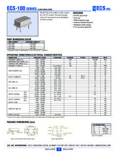
Transcription of OPERATING CONDITIONS / ELECTRICAL …
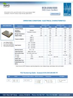
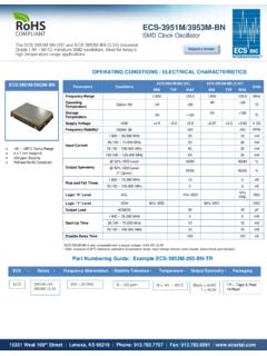
1 Parameters CONDITIONS ECS- 2018 (+ ) Units MIN TYP MAX Frequency Range MHz OPERATING Temperature Standard -10 +70 C Extended (N Option) -40 +85 C Storage Temperature -55 +100 C Input Voltage VDD + + + VDC Frequency Stability* Option A 100 PPM Option B 50 PPM Option C 25 PPM Input Current ~ MHz mA ~ MHz mA ~ MHz mA Stand-by Current Pin 1 = VIL 10 A Output Symmetry @50% VDD Level 45/55 % Rise and Fall Times 10% VDD to 90% Level 10 ns 0 Level VOL 10% VDD VDC 1 Level VOH 90% VDD VDC Output Load CMOS 15 pF Disable Delay 150 ns Startup Time 10 ms Aging 5 PPM Part Numbering Guide: Example ECS- 2018 -200-BN-TR ECS- 2018 ( ) subminiature SMD oscillators. Ideal for today s high density applications. ECS- 2018 SMD Clock Oscillator OPERATING CONDITIONS / ELECTRICAL CHARACTERISTICS 15351 West 109th Street | Lenexa, KS 66219 | Phone: | Fax: | ECS- 2018 Low Voltage HCMOS x mm Footprint Low Current Consumption PbFree/RoHS Compliant 200 = 20 MHz ECS 2018 = + Request a Sample A = 100 ppm B = 50 ppm C = 25 ppm Blank = -10 ~ 70 C M = -20 ~ +70 C N = -40 ~ +85 C * Note: Inclusive of 25 C tolerance, OPERATING temperature, input voltage change, load change, shock and vibration.
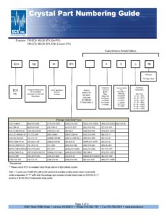
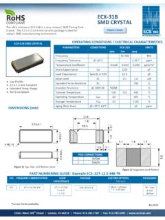
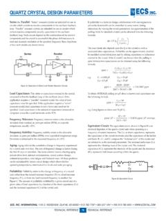
2 ECS - Series - Frequency Abbreviations - Stability Tolerance - Temperature - Packaging TR = Tape & Reel 1K/Reel Tri-State Control Voltage Pad 1 Pad 3 Open Oscillation VIH 70% VDD Min. Oscillation VIL 30% VDD Max. No Oscillation Note: Internal crystal oscillation to be halted (Pin #1=VIL) Pin Connections #1 Tri-State #2 Ground #3 Output #4 VDD Package Dimensions (mm) Figure 1) Top, Side, and Bottom views 15351 West 109th Street | Lenexa, KS 66219 | Phone: | Fax: | Figure 2) Land Pattern Package Data Item Description Lid Metal Base Ceramic Sealing AuSn Terminal Tungsten (metalized) Plating Gold/Nickel (Surface)/(Under) RoHS Compliant (Pb Free) ECS- 2018 SMD Clock Oscillator Tape Dimensions (mm) Figure 3) Pocket Tape Dimensions ECS- 2018 SMD Clock Oscillator 15351 West 109th Street | Lenexa, KS 66219 | Phone: | Fax: | Figure 4) Suggested Reflow Profile