Transcription of OPERATING, INSTALLATION, AND SERVICE …
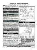
1 PAGE: 1 LP-41 REV: 9/26/08membergamagamaOPERATING, installation , ANDSERVICE manual FOR THE VOYAGER GAS FIRED WATER HEATERSUPER HIGH EFFICIENCY GAS FIRED WATER HEATING COMBINATION APPLIANCEANSI Z BY:Visit our website at: 2008, 2006, 2005, 2004 Heat Transfer Products, : 2 Recovery on rating plate is based at 94% thermal efficiency at 100 degrees Fahrenheit rise, as required by REFERENCE VOYAGER MODEL NUMBERS, PLEASE USE THE FOLLOWING GUIDELINES:CONNECTION SIZES ARE 1 1/2" NPT DOMESTIC INLET, DOMESTIC OUTLET FOR THE 80 & 119 GALLON : These overall dimensions are approximate within +/ 1".
2 Heat Transfer Products reserves the right to change specifications or discontinue models without "27-1-4"405 "SSV199-80R72"23-1-4"235 "SSV160-119R74"27-1-4"405 "SSV160-80R72"23-1-4"235 "SSV130-119R74"27-1-4"405 "SSV130-80R72"23-1-4"235 "MODELINPUTFIRSTHOURRATINGVENTSIZERECOVE RYEFFIC. %SSV199-119R199,0003353"94%SSV199-80R199 ,0003003"94%SSV160-119R160,0002703"94%SS V160-80R160,0002503"94%SSV130-119R130,00 02502"94%SSV130-80R130,0002202"94%SPECIF ICATIONSMODELGALLONCAPACITYINPUTBTU/HRNA TURAL &LP GASTEMPERATURE RISE IN DEGREES FAHRENHEIT405060708090100110120130140 SSV199-119R119199, , , , , , , TypeGal.
3 (Deg. F.)Temperature(Degrees Fahrenheit)R = 160S = 180 WarrantyA = 6 yrs. parts; 6 yrs. comm.; 10 yrs. = 1 yr. parts; 3 yrs. comm.; 10 yrs. temperature over 125 degrees F. can cause severe burns instantly,or death from scalds. Children, disabled, and elderly are at highest riskof being scalded. See instruction manual before setting temperature atwater heater. Feel water before bathing or showering! Temperaturelimiting valves are : 3- Do not store or use gasoline or other flammable vapors and liquids in the vicinity of this or any other appliance;WHAT TO DO IF YOU SMELL GAS:-Do not try to light any appliance;- Do not touch any electrical switch; do not use any phone in your building;- Immediately call your gas supplier from a neighbor's phone;-Follow the gas supplier's instructions;- If you cannot reach your gas supplier; call the fire department.
4 - installation and SERVICE must be performed by a qualified installer, SERVICE agency or the gas a location for your water heater centralized to the piping system, along with consideration to vent pipe length. As the length ofvent pipe increases the firing rate of the appliance decreases. You must also locate the Voyager where it will not be exposed to freez-ing temperatures. Additionally, you will need to place the water heater so that the controls, drain, inlet/outlet, and gas valve are easilyaccessed. This appliance must not be installed outdoors, as it is certified as an indoor appliance, and must be kept vertical and on alevel surface.
5 Also, care must be exercised when choosing the location of this appliance; where leakage from the relief valve, leakagefrom related piping, or leakage from the tank or connections, will not result in damage to the surrounding areas or to the lower floors ofthe building. A water heater should always be located in a area with a floor drain or installed in a drain pan suitable for waterheaters. Proper clearance must be provided around the Voyager as follows: Sides, bottom, top, and back are 0" (zero clearance).Front of the appliance needs 24" SERVICE clearance minimum. This front SERVICE may be achieved by a non-rated or combustible dooror access panel; providing the 24" SERVICE clearance is achieved when the door is opened or panel is removed.
6 Under no circum-stances, shall Heat Transfer Products Inc. be held liable for any such water damage whatsoever. This water heater must notbe located near flammable liquids such as gasoline, adhesives, solvents, paint thinners, butane, liquefied propane, etc.; asthe controls of this appliance could ignite those vapors, causing an AND PRESSURE RELIEF VALVEA temperature and pressure relief valve is installed into the marked port (upper right), we recommend a WATTS 100XL-4 valve orequivalent for 100,000 BTU models or below input, 40XL5 valve or equivalent for 130,000 BTU models or above input, meeting therequirements for relief valves for hot water heaters as per ANSI by a nationally recognized lab that maintains a periodicinspection of production of such listed safety device.
7 The pressure rating of the valve must not exceed the listed working pressure ofthis appliance, and must be rated to the proper BTU/hr capacity of the water heater. Do not, under any circumstances, thread a capor plug into the relief valve! Explosion, serious injury or death may result!Relief valve piping must be directed to the floor or toan open drain, but not connected directly. There must be a 6" space between the outlet of relief valve piping and drain or floor. Do nothook up to drain system directly without an air relief valve must be periodically checked for proper TANKA potable hot water expansion tank may be required to offset the water expansion as the water is heated.
8 In most city plumbing sys-tems, the water meter has a no return or back flow device built into the system to prevent back flowing of water back into city require back flow preventers on all incoming water supplies. Under these circumstances, you will need a hot water expansiontank listed for potable water use. The expansion tank should be located on the cold inlet piping close to the water INFORMATION IN THESE INSTRUCTIONS MUST BE FOLLOWED EXACTLY, A FIRE OREXPLOSION WILL RESULT, CAUSING PROPERTY DAMAGE, PERSONAL INJURY, OR expansion tank must be suitable for hot potable water.
9 Serious injury could resultPAGE: 4 DOMESTIC WATER CONNECTIONThe domestic water connections must be installed in accordance to all local and national plumbing codes, or any applicable standardwhich prevails. The inlet and outlet ports of the Voyager are 1" on 45 gallon models. On the 80 and 119 gallon models, the inlet andoutlet ports are 1 ". On the cold inlet, (bottom left), install a 1" brass tee on 45 gallon models, or a 1 " tee on 80 and 119 gallonmodels. On the run of the 1" brass tee, install with pipe sealant compound, a 1" brass drain cock or equivalent. Into the branch of the1" or a 1 " brass tee, install a copper male adapter to match your copper plumbing system.
10 For convenience, you may install a sweatshut off valve and a union in the cold inlet piping to ease servicing in the future. If there is a back flow preventer, or any type of a noreturn valve in the system, then you must install an additional tee here for a suitable potable hot water expansion tank. In the hot out-let, (top left), install a suitable adapter to match the copper tubing of the plumbing system. A thermal trap or heat trap loop may beinstalled here, to provide additional energy savings and prevent the thermal siphoning of domestic hot water. Refer to pages 22 to 26for typical LOW WATER CUT-OFF NORMAL OPERATIONA low water cut-off switch has been added to the High Efficiency Water Heater to stop the possibility of dry firing the water heater anddamaging the internal heat exchanger.