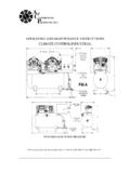
Transcription of Operating Instructions - Rickson
1 Operating Instructions Reactive Power Control Relay RM 2106/12 2 3 Safety and warning notices !!! Important !!! Read this before commissioning!!! The Operating Instructions should be read carefully before the device is assembled, installed and put into operation. Installation and commissioning should only be carried out by appropriate specialists in accordance with existing regula-tions and provisions. The operator must ensure that all operatives are familiar with these Operating Instructions and proceed accordingly. The device conducts mains voltage and should not be opened. If the device is obviously damaged, it should not be installed, connected or commissioned.
2 If the device does not work after commissioning, it should be disconnected from the mains again. Any other laws, standards, guidelines, etc. regarding this product must be observed. The commissioning and safety information for the power factor correction system should also be observed. 4 Figure 1: Front view a Display for active capacitor stages b Display for inductive or capacitive Operating status c Digital display d LED indicates regenerative power e Display for current or historical alarms f LED lights up in setup mode g LED lights up in manual mode h Multifunctional button (see Operating Instructions ) i Selection key for manual mode, setup mode or automatic mode 5 Figure 2: Rear view j Connection for the current trans-former k Optional connector for improved measurement of harmonic wave l Connector for power supply to the control relay m Connectors for the control contacts that switch the contactors.
3 The shared pole is connected to terminal L . n Typical connection 6 Contents Page Page1. Introduction ..7 How to use these Operating Instructions ..7 Scope of functions ..7 2. Installation and Installation ..8 Voltage connection ..8 Current transformer connection ..8 Meas measuring voltage Switching contacts ..9 Alarm contact ..9 Standard Extended connection ..11 Connection with voltage Connection in special cases ..13 3. Start-up ..14 Initial start-up ..14 Subsequent start-up ..15 4. Control relay setup ..16 Target power factor setting .. -1- ..17 Overcurrent switch off .. -2- ..19 Relay 6 as alarm relay.
4 -3- ..19 Automatic response current -4- ..20 Response current .. -5- ..20 Relative value of the switch outputs .. -6- ..22 Service .. -7- ..22 5. Functioning and operation .. 23 Automatic control mode .. 23 Displaying the total harmonic distortion factor .. 23 Check System .. 23 Manual 24 6. Alarms and troubleshooting .. 25 Connection errors .. 25 E3 - No capacitors .. 25 E1 - Defect capacitor stages .. 25 E2 - Incorrect connection .. 25 I = 0 - No current in current path 25 Connection messages .. 26 A2 - Incorrect connection that can be corrected 26 A1 - Relative value of the switch output.
5 26 Alarms in automatic control operation .. 26 E4 - Harmonic overcurrent in the capacitor .. 26 E5 - Target power factor not reached .. 27 E1 - Defect capacitor stages .. 27 U = 0 - No measuring 27 I = 0 - No measuring current .. 27 Other errors .. 27 Troubleshooting .. 28 7. Technical 29 7 1. Introduction The reactive power control relay RM 2112 and RM 2106 respectively is capa-ble of measuring the reactive power and active power of the connected mains network. W orking in conjunction with a power factor correction system, the de-vice controls the programmed target power factor by activating or deactivating capacitors.
6 How to use these Operating in-structions Important: It is essential that you read section 2 Installation and connection and section 3 Start-up before installing the control relay. The functions of the control relay are also described in brief in section Scope of functions . The setting options for the control relay are described in section 4 Control re-lay setup . Section 5 Functioning and operation explains how the control relay works and how to operate it. Section 6 Alarms and troubleshoot-ing describes alarms and error mes-sages of the control relay. Troubleshooting information is also provided there.
7 Scope of functions Below is a brief overview of the various functions of the device: 12 switching contacts at RM 2112 and 6 switching contacts at RM 2106 Power factor display Total harmonic distortion factor display (voltage thd) Semi-automatic connection detection Automatic detection of the capacitor stages Comprehensive connection analysis Patented characteristic avoiding over-compensation for low active power Four-quadrant regulation Cyclic switching of all capacitor stages of the same capacity Reactive power requirement-dependent switching delay time Optional monitoring of the harmonic overcurrent in the capacitor Deactivation at zero voltage or zero current Alarm signals for.
8 - failure to reach the target power fac-tor - overcurrent in the capacitor - defects at capacitor stages 8 2. Installation and connection The reactive power control relay RM 2112 and RM 2106 respectively can be connected in a number of different ways. The main connection methods are described below. Important information: The control relay should be discon-nected from the mains during installation. Installation The reactive power control relay is in-stalled from the front in a control panel space measuring 138 x 138mm and is fixed in place using the mounting screws of the front panel.
9 As accessories (protection kit; see section 8) insulated fixing screws are available. These can be used to install the control relay into switchgear cabinets and cubicles of protective class II. Also a sealing ring is part of the protection kit, which must be used when installing the control relay in switchgear cabinets and cubicles of protection class IP 54. The pre-assembled fixing clamps ensure speedy and secure assembly. The elec-trical connection is created by means of plug-in connectors which are also in-cluded in the delivery. Voltage connection Reactive power control relay obtains its voltage supply via terminals L and N (see figure 2, item l ).
10 A phase conductor is to be connected to terminal L and neutral conductor to ter-minal N . For advanced connection variations see sections to Important information: The reactive power control relay is designed for voltage supplies of up to 240 VAC. The connections for the supply volt-age are to be fused externally with 4A max. In the case of mains networks that do not facilitate voltage tapping in the 220 VAC to 240 VAC range (either phase/phase or phase/neutral), a voltage transformer must be used for the power supply for the control relay. (See section ) Current transformer connection Outputs S1 and S2 of the current trans-former are connected to terminals S1 and S2 (Figure 2, item j ) of the control relay.