Transcription of OPERATING MANUAL - The Repeater Builder's …
1 YAESU MUSEN CO., Nakameguro, Meguro-Ku, Tokyo 153-8644, JapanYAESU Edwards Rd., Cerritos, CA 90703, EUROPE Box 75525 1118 ZN, Schiphol, The NetherlandsYAESU UK 12, Sun Valley Business Park, Winnall CloseWinchester, Hampshire, SO23 0LB, GERMANY GmbHAm Kronberger Hang 2, D-65824 Schwalbach, GermanyYAESU HK Floor Tsim Sha Tsui Centre, 66 Mody Rd.,Tsim Sha Tsui East, Kowloon, Hong KongOPERATING MANUALI ntroduction .. 1 Controls & Connectors .. 2 Accessories & Options .. 3 Basic Operation .. 4 Battery Pack Installation and Removal .. 4 Antenna Installation .. 5 Switching Power ON and OFF .. 6 Adjusting the Volume Level .. 6 Squelch Setup .. 6 Transmitting .. 6 Frequency Navigation.
2 7 Changing the Transmitter Power Level .. 7 Changing the Channel Steps .. 7 Repeater Operation .. 8 Automatic Repeater Shift (ARS) .. 8 MANUAL Repeater Shift Activation .. 8 Setting Repeater Tx Offset .. 9 Checking the Repeater Uplink (Input) Frequency .. 9 Keyboard Locking .. 9 Advanced Operation .. 10 VFO Split Mode .. 10 Receive Battery Saver Setup .. 10Tx Battery Saver .. 11 Keypad/LCD Illumination .. 11 Automatic Power-Off (APO) Feature .. 12 Checking the Battery Voltage .. 12 Disabling the BUSY/TX LED .. 12 Busy Channel Lock-Out (BCLO) .. 12 Disabling the Key pad Beeper .. 13 Programming the Key Functions .. 13 Transmitter Time-Out Timer (TOT).
3 13 Tone Calling (1750 Hz) .. 14 ANI Operation (Automatic Number Identification) .. 14 CTCSS Operation .. 15 DCS Operation .. 16 Tone Search Scanning .. 17To scan for the tone in use .. 17 CTCSS/DCS Bell Operation .. 17 Memory Operation .. 18 ContentsMemory Storage .. 18 Storing Independent Trasmit Frequencies ( Odd Splits ) .. 18 Memory Recall .. 18 Memory Offset Tuning .. 19 HOME Channel Memory .. 19 Labeling Memories .. 19 Masking Memories .. 20 Memory Only Mode .. 20 Scanning .. 21 Setting the Scan Resume Technique .. 21To set the Scan-Resume mode .. 21 VFO Scanning .. 21 Memory Scanning .. 22 How to Skip (Omit) a Channel During Memory Scan Operatin.
4 22 Programmable (Band Limit) Memory Scan (PMS) .. 22 Automatic Lamp Illumination on Scan Stop .. 23 Band Edge Beeper .. 23 Smart Search Operation .. 23 Setting the Smart Search Mode .. 24 Storing Smart Search Memories .. 24 Priority Channel Scanning (Dual Watch) .. 24 DTMF Operation .. 26 MANUAL DTMF Tone Generation .. 26 DTMF Autodialer .. 26To send the telephone number .. 26 ARTS Operation .. 27 Basic ARTS Setup and Operation .. 27 ARTS Polling Time Options .. 28 ARTS Alert Beep Options .. 28CW Identifier Setup .. 28To activate the CW identifier .. 29 Interface of Packet TNCs.
5 30 Reset .. 30 Cloning .. 31 Set Mode .. 32 Specifications .. 41VX-150 OPERATING MANUAL1 The VX-150 is an ultra compact FM hand-held providing up to five watts of RF power anda wealth of convenient features for the 2m amateur band. The VX-150 has rubber gasketseals around all external controls and connectors to help keep out dust and rain or spray,assuring years of reliable operation even in harsh multi-function keys provide the ultimate in programmability, with 199 freely tun-able memories and two VFOs. All memories store Repeater shifts or separate tx/rx frequen-cies, CTCSS (Continuous Tone Controlled Squelch System) or DCS status. You also getone instant-recall Home channel memory and ten special purpose memories for limitedsubband tuning/scanning.
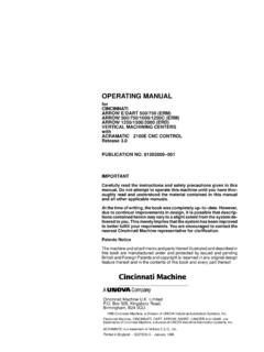
6 Busy channel band or selective memory scanning is providedalong with priority channel monitoring; 1 MHz up/down stepping; ARS (automatic re-peater shift) when tuned to Repeater subbands; plus a top panel rotary dial for memory andfrequency selection. The keypad serves as a DTMF encoder during transmission, and up to9 DTMF memories can store 16 digits each for quick playback of commonly used liquid crystal display shows seven frequency digits, memory selection, CTCSS tonefrequency, and includes a bargraph S/PO meter. Yaesu s power saver system can be set bythe operator for optimum sampling/standby ratio, or can be turned off for packet our new APO (Automatic Power Off) system shuts off the transceiver to avoid deadbatteries if you doze off or are called away under difficult conditions is simplified by a lamp button illuminating the displayand backlit translucent keypad, diatonically assigned function-dependent keypad read this MANUAL carefully to gain a full understanding of the features of the OPERATING MANUAL2 Controls & ConnectorsKeypadMicSpeakerEXT DCMIC/SP JackBattery Pack LatchPTT ButtonBUSY/TX Indicator LampSQL ControlDIAL Rotary SelectorMonitor (Burst)
7 ButtonLAMP ButtonLCD (Liquid Crystal Display)VOL/OFF ControlANTENNA JackS- and TX Power MeterAuto Power OFF ActiveLOCK Feature ActiveLOW PowerAlt Key ActiveMemory NumberorVFO SelectionTone Encoder/Squelch EnabledDigital Coded SquelchDTMF Memory ModeMemory SkipBELLP riority Channel ScanningRepeater ShiftMemory ModeFrequencyVX-150 OPERATING MANUAL3 ACCESSORIES SUPPLIED WITH THE VX-150 FNB-64Ni-Cd Battery Pack ( V, 700 mAh)NC-72A/B/C/F/UBattery CharegerBelt ClipAntennaOperating ManualWarranty CardAVAILABLE OPTIONS FOR YOUR V, 1100 mAh Ni-Cd Battery V, 700 mAh Ni-Cd Battery PackFBA-25 Compact Dry Cell Battery Case for 6 AA-size cellsCD-16 Desktop Rapid Charger (requires CA-24 and PA-23)NC-72A100 VAC Compact Wall Charger for FNB-64NC-72B120 VAC Compact Wall Charger for FNB-64NC-72C230-240 VAC Compact Wall Charger for FNB-64NC-72F220 VAC Compact Wall Charger for FNB-64NC-72U230 VAC Compact Wall Charger for FNB-64NC-73 Desktop Rapid ChargerMH-34B4 BExternal Hand Speaker/MicrophoneMH-37A4 BEarpiece/MicrophoneVC-25 VOX HeadsetE-DC-5 BDC Cable w/Noise FilterE-DC-6DC Cable.
8 Plug and wire onlyCA-24 Charger SleevePA-23AC AdapterCN-3 BNC-to-SMA AdapterCT-44 Microphone AdapterYHA-62 Rubber flex antennaCT-27 Cloning CableAvailability of accessories may vary: some accessories are supplied as standard per localregulations and requirements, others may be unavailable in some regions. Check with yourYaesu dealer for additions to the above & OptionsVX-150 OPERATING MANUAL4 Basic OperationBATTERY PACK INSTALLATION AND REMOVALTo install the battery, hold the transceiver with your left hand, so your palm is over thespeaker and your thumb is on the top of the belt clip. Insert the battery pack into the batterycompartment on the back of the radio while tilting the Belt Clip outward, then close theBattery Pack Latch until it locks in place with a Click.
9 To remove the battery, turn theradio off and remove anyprotective cases. Open theBattery Pack Latch on thebottom of the radio, thenslide the battery downwardand out from the radio whileunfolding the Belt not attempt to open any of the rechargeable Ni-Cd packs, as they could explode ifaccidentally the battery has never been used, or its charge is depleted, it may be charged by connect-ing the NC-72A/B/C/F/U Battery Charger, as shown in the illustration, to the EXT DCjack. If only 12 ~ 16 Volt DC power is available, the optional E-DC-5B (with its cigarettelighter plug) or E-DC-6 DC Adapter may also be used for charging the optional FNB-V57 high-capacity battery can not be charged using the NC-72; pleaseuse the optional OPERATING MANUAL5 ANTENNA INSTALLATIONThe supplied antenna provides good results over the entire frequency range of the trans-ceiver.
10 However, for enhanced coverage in remote areas, an external mobile or base stationantenna may prove install the supplied antennaHold the bottom end of the antenna, then screw it onto the mating connector on the trans-ceiver until it is snug. Do not over-tighten by use of extreme :mNever transmit without having an antenna installing the supplied antenna, never hold the up-per part of the antenna while screwing it onto the matingconnector on the that a large base-station antenna will haveconsiderably more gain than the supplied rubber flexantenna, and this added gain may degrade the ability ofthe VX-150 to resist intermodulation-type interference. The installation of a suitable144-148 MHz bandpass filter in the coaxial line to a base station will usually eliminatesuch interference, if OperationVX-150 OPERATING MANUAL6 SWITCHING POWER ON AND OFF Be sure the battery pack is installed.