Transcription of OPERATION 2 - Marine Air Conditioning
1 Box 430 Milford, VA 22514 Phone (804) 633-9454 FAX (804) 633-5499 Distributed By:Taylor Made Environmental, Box 15299 Richmond, Virginia 23227-0699 USAT elephone: 804-746-1313 Facsimile: 804-746-7248E-mail: 4-28-00L-0261 DIRECT EXPANSION DIRECT EXPANSION DIRECT EXPANSION DIRECT EXPANSION DIRECT EXPANSION SYSTEMSSYSTEMSSYSTEMSSYSTEMSSYSTEMSDX Built-In Air Cooled A/C Systems INSTALLATION OPERATION 2 For LP-10 AThis manual contains essential safety information concern-ing the safe and proper installation of Cruisair direct expan-sion air Conditioning systems. It is very important that youread and understand the contents of this manual thor-oughly before attempting to install any Cruisair there are any statements in this manual that you do notunderstand, contact Taylor Made Environmental Applica-tions Department for assistance. Phone (804) 746-1313,Fax (804) 746-7248 (8:00am - 5:00pm United StatesEST).
2 NOTICEAs of July 1, 1992, United States federal law prohibits theintentional release of refrigerant gases into the environ-ment, including the R-22 refrigerant used in Cruisair airconditioning systems. Special care must be taken wheninstalling, charging and servicing Cruisair equipment toprevent any loss of does not recommend the practice of using refriger-ant to purge air and moisture from the system at installa-tion. This formerly used practice of purging is in violation ofUnited States federal manual covers installation procedures for Cruisairdirect-expansion air Conditioning addition, there are specific installation sheets for somemodels which may be shipped with Cruisair air conditioningequipment, providing additional details for specific 1: Description of Basic Components .. 4 Basic Principles .. 4 Cooling Unit .. 4 Controls/Switches .. 4 Condensing Unit.
3 4 Figure 1. SA 3 Series Control .. 4 Figure 2. SMX Series Keypad .. 4 Chapter 2: Installation of Basic Components .. 5 Cooling Unit .. 6 Control or Switch Assembly .. 6 Condensing Unit .. 6 Installation Kit .. 7 Figure 3. Minimum Grill and Free Air .. 5 Figure 4. Diagram of Flared Joint .. 7 Figure 5. Refrigerant Line Sizes .. 8 Chapter 3: Start-Up Procedures - Final Inspection .. 9 Figure 6. Wire and Breaker Size .. 9 Chapter 4: Start-Up Procedures - Intitial Charging of A New System .. 10 Required Tools .. 10 Field Charging a System .. 11 Removing Refrigerant from a System .. 11 Figure 7a. Charging Pressure Charts for Equipment Built in 1994 and After .. 12 Figure 7b. Charging Pressure Charts for Equipment Built Prior to 1994 .. 13 Chapter 5: Start-Up Procedures - Final Check-Out and Start-Up .. 14 Chapter 6: General OPERATION .. 15 Operating Instructions - Rotary Knobs.
4 15 Operating Instructions - SMX Series Controls ..16 Chapter 7: Maintenance .. 17 Cooling Unit and Switch Assembly .. 17 Condensing Unit .. 17 Chapter 8: System Failure Troubleshooting Guide .. 18 Chapter 9: System Charging Troubleshooting Guide .. 19 Chapter 10: Installation Wiring Diagrams .. 20 Index of Diagrams .. 31 Table of ContentsCHAPTER 1: Description of Basic ComponentsBasic PrinciplesThe Cruisair air Conditioning system consists ofthree basic components and, in some cases,several accessory parts. They are: (1) coolingunit; (2) control or switch assembly; and (3)condensing unit. This instruction manual willdescribe and explain the function of the basicparts of a Cruisair system and will outline theinstallation, interconnection and startup of acomplete system. It also includes maintenanceand OPERATION of Cruisair equipment in UnitThe cooling unit is a refrigerant to air heatexchanger coupled to a fan or blower which islocated in the space to be cooled.
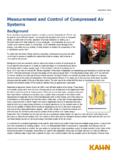
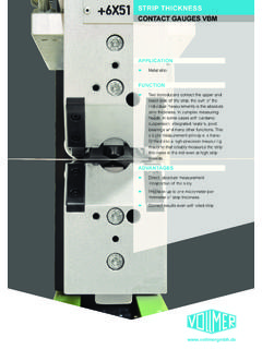
5 A cooling unit issometimes referred to as an evaporator or a cooling coil , but in this manual, we will use theterm cooling unit . The cooling unit is constructedof a series of copper tubes held in place byvertical aluminum fins. Inside these tubes, therefrigerant expands to produce a chilling effect byabsorbing the heat in the air. This air is forcedthrough the coil by the fan or are two basic types of controls andswitches used with Cruisair systems: the SMXseries of microprocessor controls and the SAFigure 1. SA 3 Series ControlFigure 2. SMX Series Keypadfamily of rotary knob switch assemblies. The SAtype switch assembly has rotary knobs for control-ling the system. Figure 1 shows a typical SAswitch SMX series controls are advanced micro-processor based systems, with more than 20 userprogrammable functions. These functions aredescribed in the SMX series owner s 2 shows an SMXII control UnitThe condensing unit consists of the refrigerantcompressor, the refrigerant receiver, the refriger-ant to air heat exchanger or condenser, con-denser fan or blower, the associated electricalcomponents, and the system service basic function of the condensing unit is tocompress the expanded refrigerant, flowing backfrom the cooling unit to the compressor, to a highpressure state.
6 The compressed refrigerant thenpasses through the heat exchanger (condensercoil) where it gives up the heat which wasabsorbed in the cooling coil. It is then condensedto a liquid state as it flows to the liquid receiverand the process of flow back to the cooling unit ModeSlowFanFast77 The following instructions should be followed, intheir proper sequence, when installing Cruisairequipment. Read and understand the instruc-tions in this manual before UnitIn all installations, the cooling unit must beinstalled so the air discharge grill is installed ashigh as possible, (minimum three feet above thefloor level). The cooling unit must be installedwith the condensate drip pan positioned at thebottom of the unit so the water dripping from theevaporator coil collects in it before dischargingto a suitable drain outside.
7 The cooling unit drainmust be installed so the drain tube makes animmediate 1 drop after leaving the drain discharge air grills located high, returnair grills should be located as close to the flooras possible to provide the best pattern of airflow. Avoid locating the return air grill in closeproximity to the discharge grill since the result-ing short circuiting effect of the air flow willimpair the effectiveness of the units with model number prefixesEFB, EBH, or EFL should be mounted as highas possible, directly behind the discharge 2: Installation Of Basic ComponentsCentrifugal or blower type cooling units, modelnumber prefixes EBS, EBO, EHBO, EBL or EHBL,should be mounted low, near the return air grill,and the discharge air ducted to the discharge grillmounted at a high cooling unit must be installed so there isan adequate path for the air to re-circulate freelyinto the unit from the space being cooled.
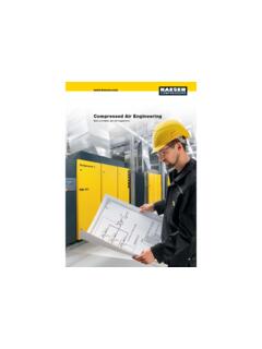
8 It isimportant that the cross sectional area of alldischarge grills be at least equal to the coil facearea of the discharge of the cooling unit exception is the centrifugal blower type cross sectional area refers to the free air area of a discharge air grill rather than the totalarea as determined by the overall measurementof the grill itself. For instance, if a grill is made ofexpanded metal, perhaps only 50% of the area isopen for the passage of air. The metal web itselfwill block air from passing through the other 50%.In such cases, the total area of the grill must bedoubled to achieve the required open this carefully when selecting a return air grills used should be the typewhich have removable filters so they can be5 Minimum Grill And Free Air AreaEVAPORATORDUCTGRILL AREAFREE AIR AREATypeBTU sSize (Sq. In.) SupplyReturn (70%) (Sq. In.) Supply (60%)EBL16,0002 @ 51442 @ 491012 @30 EBO4,0004643245197,00057249513010,000610 060703614,0007144801014816,0007144801014 8 EBS14,0007144801014816,00071448010148 EFB10,000NA100100706014,000NA14414410187 16,000NA14414410187 EBH14,000NA1441441018716,000NA1441441018 7 EFL1,000NA4040282414,000NA128128907716,0 00NA1281289077 Figure 3.
9 Minimum Grill and Free AirCondensing UnitCruisair condensing units are designed to beinstalled in a compartment ventilated to theoutside. Air entry and exit openings to the exteriorshould be protected by rain proof louvers or should be provided on all sides of the unitto allow air to enter it for cooling the refrigeration components are hermeticallysealed and all electrical components are sparkproof for maximum safety. Make sure the woodbase is positioned at the bottom of the unit in ahorizontal plane. Fasten the condensing unitwood base securely and in such a way that theunit can be removed for service if and cleaned easily. The filter materialshould be a type which will not cause a significantinlet air flow pressure drop. For all discharge airapplications, wood or plastic frames are recom-mended. Aluminum frame grills will become coldand may produce secondary condensation thatwill drip from the grill Figure 3 to determine the minimum grilland free air areas for each model cooling or Switch AssemblyThe control or switch assembly is supplied as aseparate item.
10 The rotary switch assembly hasthree knobs and the plate is printed either forhorizontal or vertical installation. It is designed tobe mounted in an opening cut on the job and isfastened from the front with four screws. Thewiring from the switch assembly terminates in acolor coded terminal strip that should be securelymounted in a suitable place. Electrical connec-tions for all systems are typically the of the SA type controls is covered inChapter thermostat in the switch assembly has a10 foot capillary tube leading from it to the tem-perature sensing bulb. This bulb must be locatedin the system s return air stream so that the bulbis exposed only to the air returning from the spacebeing SMX control system uses a TemperatureSensing Element (TSE) to control the OPERATION ofthe system. Like the thermostat bulb on the SAtype control, this TSE must be installed in thereturn air path of the conditioned air.