Transcription of OPERATION AND MAINTENANCE MANUAL UF-6 …
1 OPERATION AND MAINTENANCE MANUAL UF-6-HF ULTRAFILTRATION SYSTEM Con-Serv Manufacturing 805 West Brannen Road Lakeland, FL 33813 (800) 868 9888 System OPERATION and MAINTENANCE MANUAL Page 1 Introduction This MANUAL includes the operating instructions and recommended MAINTENANCE practices for safe and effective use of an Ultrafiltration (UF) system capable of producing 6 gpm of filtered water. The system is completely self-contained and includes equipment required for unattended automatic OPERATION . All equipment is skid-mounted and controlled by a single local control system. It is recommended that the user read this entire MANUAL and closely study the equipment, instrumentation, and controls before operating the UF system. Technologies Utilized Microfiltration A small microfilter is installed on the UF system as pre-treatment for the ultrafiltration membrane. It is a screen-type mesh filter rated for about 80 mesh (200 micron) filtration.
2 Ultrafiltration - An ultrafiltration (UF) system uses hydrophilic capillary membranes to separate a high percentage of suspended and dissolved molecules. Only certain types of molecules, like water, can pass through the membrane. Other larger molecules, like organic compounds, proteins, oils, and suspended solids do not pass through the membrane and are left behind. The membrane is made of thin hollow-fibers with an inside diameter of between and mm with microscopic pores that let water pass through while acting as a barrier to stop dissolved and suspended particles. The UF membrane used on the system are an outside-in configuration where the feed water stays on the exterior of the membrane fiber and the filtered water passes into the core of the hollow fiber. The UF membrane can be backwashed by pumping filtered water in opposite direction of the feed flow through the inside of the fiber.
3 The efficiency of the backwash can be enhanced by adding chemicals (such as acid or hypochlorite) into the backwash water. As shown in Figure 1, water permeates the minute pores of the membrane and is delivered as purified product water. The impurities in the water do not pass through the membrane, and are instead concentrated in the reject stream that is flushed to the drain or recycled back to the feed water. The system is designed to operate in conjunction with two customer-supplied tanks; the Raw Water Tank and the UF Filtrate Tank. Ultrafiltration System OPERATION and MAINTENANCE MANUAL Page 2 Specifications The UF system is designed to produce up to 6 GPM of effluent per feed water conditions in accordance with Table 1. The UF system is shown in Figure 2 below. Raw Water Capacity 7 GPM (450 l/h) Treated Water Capacity 6 GPM (350 l/h) Dimensions 51 L x 32 W x 73 H Approx.
4 Dry Weight 900 lbs Approx. Operating Weight 1,000 lbs Ambient Temperature 5 35 C Figure 1- The Ultrafiltration Process using Hollow-Fiber Membranes System Requirements and Operating Guidelines Piping Connections The following connections are required to operate the UF system. Refer to the General Arrangement drawing in Appendix D for more information. Raw Water Inlet A flange connection of is provided for inlet of the untreated water from the Raw Water Tank. Due to the height of the raw water tank, this connection should have some nominal amount of pressure (at least 1-2 psi). Ultrafiltration System OPERATION and MAINTENANCE MANUAL Page 3 Temperature of the feed water must not exceed 113 F (45 C).
5 The raw water inlet flow to the UF system should not exceed 10 gpm. Concentrate Recycle Outlet - A flanged connection of 1/2 is provided for recycle of the concentrate water back to the Raw Water Tank. This outlet should have less than 10 psu pressure. Filtered Water Outlet A flanged connection of 3/4 is provided for outlet of the treated wastewater to the UF Filtrate Tank. This outlet is not pressurized. Concentrate Outlet/Drain A flanged connection of is provided for outlet of the UF concentrate and UF backwash effluent. This outlet is not pressurized, therefore the tubing or piping used for discharge from this drain pipe should be run to an open drain in a free and unrestricted manner. Any restrictions or blockage in the drain can cause backpressure which can overflow the storage tanks. Membrane Drain A flanged connection of is provided for draining of the UF membranes.
6 This outlet is not pressurized, therefore the tubing or piping used for discharge from this drain pipe should be run to an open drain in a free and unrestricted manner. Any restrictions or blockage in the drain can cause backpressure which can overflow the storage tanks. UF Filtrate Inlet A flange connection of is provided for inlet of the filtered water from the Filtrate Tank. Due to the height of the UF Filtrate tank, this connection should have some nominal amount of pressure (at least 1-2 psi). Temperature of the filtered water must not exceed 113 F (45 C). The filtered water inlet flow to the UF system should not exceed 10 gpm. Electrical Connections A single electrical connection is required for the UF system. This connection should be a 3-conductor connection, with each conductor having a diameter of at least #14 AWG ( mm2).
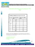
7 Since the standard electrical supply is 60Hz/220-230V/1-phase, the 3-conductors should include L1, L2, and ground. These connections should be made to the top of circuit breaker CB1 as shown in the electrical drawings included as Appendix C. The electrical service required is 20 amperes. Note: We recommend that a licensed electrician make the electrical service connection to the UF system install your unit in accordance with local and national electrical codes. Ultrafiltration System OPERATION and MAINTENANCE MANUAL Page 4 Figure 2 UF System Feed Water Requirements Nothing has a greater effect on the performance of any membrane-based filtration system than the feed water quality. For lasting performance it is important to supply the UF systems with the feed water quality shown below in Table 1. Note: The projected performance is based on feed water at a temperature of 25 C.
8 Lower feed water temperature will reduce system production. It is very important to meet the feed water requirements. Failure to do so will cause the membranes to foul and may void the warranty. Ultrafiltration System OPERATION and MAINTENANCE MANUAL Page 5 pH 2 - 11 TDS up to 10,000 mg/L TSS up to 500 mg/L Temperature 15 to 35 C Hardness < 300 ppm as CaCO3 Turbidity < 50 NTU Iron < 5 mg/L Oils and Greases < mg/L Solvents.
9 Phenols < mg/L Table 1 Recommended Feed Water Characteristics Automatic OPERATION The UF system is intended for automatic OPERATION and as such will initiate different functions without much advance indication. The user should be familiar with these automatic functions and make sure that the site conditions are suitable for automatic and unattended OPERATION . In general, it should be understood that when the system is setup for automatic OPERATION , the individual pumps and valves will start and stop automatically depending on the solution level in the three storage tanks. Raw Water Fill The Raw Water Tank will automatically be refilled if the pipe connection to the Raw Water Tank is constantly pressurized and the Raw Water Tank level is not full. UF System Start/Stop The UF system is equipped with level switches in the Raw Water and Filtrate Tanks which will be used by the local control panel to automatically start and stop the UF system.
10 Indicator lamps on the front control panel will indicate the status of the system. Start-Up The UF system is free standing and requires no special installation, however, if placed on an uneven floor, the system may vibrate. Adjustable leveling legs are supplied to facilitate installation. Carefully inspect your system before start-up. Check all plumbing and electrical connections. Connections may have loosened during shipment. Step-by-Step Setup Instructions Refer to the Control Panel Layout drawing included as Figure 3. 1. Confirm that all piping connections are made to the system and the following isolation valves are open and all customer-supplied tank drain valves are closed: Ultrafiltration System OPERATION and MAINTENANCE MANUAL Page 6 OPEN: BV01 - Raw Water Inlet BV04 / BV05 Filtrate Pump Suction / Discharge BV07 Filtrate Outlet CLOSED: BV02 / BV03 Raw Water Pump Suction / Discharge BV06 Drain 2.