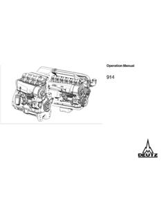
Transcription of Operation Manual TCD 2012 L04/06 V2 TCD 2013 L04/06 V2
1 Operation ManualTCD 2012 L04/06 V2 TCD 2013 L04/06 V2zRead and observe the information in thisinstruction Manual . You will avoid accidents,retain the manufacturer s warranty and havea fully functional, ready to use engine at engine is exclusively for the purposeaccording to the scope of delivery - definedand built by the equipment manufacturer (usefor the intended purpose). Any use above andbeyond this is considered improper use. Themanufacturer will not be liable for damagesresulting from this. The user will bear the solerisk in this for the intended purpose also includesobservance of the operating, maintenanceand repair instructions specified by themanufacturer. The engine may only be used,maintained and repaired by persons who arefamiliar with it and instructed in the work on the enginemay only be carried out when the engine is notrunning and has cooled doing this, make sure that the electricalsystem is switched off (remove ignition key).
2 The specifications for accident preventionwith electrical systems ( VDE-0100/-0101/-0104/-0105 Electrical protective measuresagainst dangerous touch voltages) must all electrical components tightly whencleaning with not work on the fuel system while theengine is running - Danger to (1 minute) for the engine to come to astandstill (pressure release), as system isunder high pressure: there is a - Danger the first trial run do not stand in thedanger area of the engine (danger due to highpressure of leaks) - Danger to In case of leaks immediately contactthe When working on the fuel system ensure thatthe engine is not unintentionally started duringrepairs- Danger to pertinent rules for the prevention ofaccidents and other generally recognisedsafety and industrial medicine rules must the engine is running there is a dangerof injury caused by:- rotating / hot components- engines with extraneous ignition- ignition systems (high electrical voltage)Contact must be avoided!
3 ZThe manufacturer will not be liable for damagesresulting from unauthorised modification to , manipulations to the injection and controlsystem can affect the engine s performanceand the exhaust characteristics. Compliancewith environmental regulations will no longerbe guaranteed in this not alter, obstruct or block the area of thecool air supply to the manufacturer will accept no liability fordamages resulting from DEUTZ original parts may be used whencarrying out maintenance/repair work on theengine. These have been designed especiallyfor your engine and ensure a to observe this will lead to voiding of thewarranty! Operation ManualTCD 2012 L04/06 V2 TCD 2013 L04/06 V2312 1890 enPlease enter the engine number here. This willsimplify the handling of customer service, repairand spare parts queries (see Section ).Illustrations and data in this instruction Manual aresubject to technical changes in the course ofimprovements to the engines. Reprinting andreproductions of any kind, even in part, requireour written number.
4 2005 ForewordDear customer,The liquid-cooled engines made by DEUTZ aredeveloped for a wide variety of extensive range of variants ensures thatthe respective special requirements are engine is equipped according to theinstallation, not all the parts andcomponents described in this instructionmanual are installed on your have done our best to clearly identify thedifferences, so that you can easily find theoperating, maintenance and repairinstructions relevant to your read these instructions before youstart your engine and observe the operatingand maintenance are at your service for any questions youmay have in this AG of company sideTCD 2012 L04 sideTCD 2012 L04 sideTCD 2012 L06 sideTCD 2012 L06 sideTCD 2013 L04 sideTCD 2013 L04 sideTCD 2013 L06 sideTCD 2013 L06 oil oil diagram (example) diagram (example) cable connections engine / bleeding cooling oil ambient temperature,high work carried and change oil level, changing engine oil / changing oil filter (cup) fuel pre-filter, changing / bleedingfilter cooling cooling / bleeding cooling air cyclone oil bath air air V-rib wear limit of V-rib valve clearance,setting if control piston clearancein exhaust gas recirculation (EGR) Diagram for setting valve / controlpiston clearance current suspension7.
5 Faults, causes and protection function of theelectronic engine controller the diagnosis of fault blink corrosion and setting tightening ServiceContents1 2005 GeneralDEUTZ Diesel Enginesare the product of many years of researchand development. The resulting know-how,coupled with stringent quality standards,guarantee their long service life, high reliabilityand low fuel goes without saying that DEUTZ DieselEngines meet the highest standards for en-vironmental of Running EngineShut the engine down before carrying outmaintenance or repair work. Ensure that theengine cannot be accidentally started. Risk ofaccidents!When working on the running engine, workclothing must be close industrial safety regulations whenrunning the engine in an enclosed space the work is complete, be sure to refitany panels and guards that may have fill the fuel tank while theengine is and MaintenanceSound care and maintenance practices willensure that the engine continues to meet therequirements placed on it.
6 Recommendedservice intervals must be observed andservice and maintenance work carried outconscientiously. Special care should be takenunder abnormally demanding symbol is used for all safetywarnings which, if notobserved, present a directdanger to life and limb for theperson involved. Please followthem carefully. The attention of operatingpersonnel should be drawn to these safetyinstructions. General safety and accidentprevention regulations laid down by law mustalso be original parts contact one of our authorized servicerepresentatives in the event of breakdownsor for spare parts inquiries. Our trainedspecialists will carry out repairs quickly andprofessionally, using only genuine spareparts. Original parts from DEUTZ AG arealways produced in accordance with state-of-the-art Technical Circulars listed in the instructionmanual are obtainable from your turn to the end of this Manual forfurther service description Engine Engine Lube oil Fuel coolant Electrics2 Engine description 2005 35 985 0 43 834 0 38 987 Engine Company plateThe engine type A,engine number B and thepower data are stamped on the company engine type and number must be statedwhen purchasing spare Location of company plateThe company plate Cis fixed to the cylinderhead cover or the description 2005 43 833 0 38989 0 The engine number is stamped on the crankcase(arrow)
7 And on the company Engine Cylinder numberingThe cylinders are counted consecutively, startingfrom the Engine type2 Engine description 2005 43 302 Engine Operation sideTCD 2012 L04 2V1 Oil filler2 Combustion air inlet3 Cover4 Fan5 Generator6 Fuel pump7 Tension pulley with torsion spring8 Oil cooler9 Exchangeable fuel filter10 Exchangeable lube oil filter11 Oil tray12 Hydraulic pump or compressor mountingpossibility13 Flywheel14 Crankcase bleeding valve15 Transport eyes16 Charge air pipe17 Fuel control unit2 Engine description 2005 44 303 Engine Starter sideTCD 2012 L04 2V18 Exhaust manifold19 Turbocharger20 Oil filler (optional)21 Engine mounting22 Oil return line from turbocharger23 Relay (starter)24 V-rib belt25 coolant inlet26 coolant outlet27 coolant pump28 Connection cabin heater orcompensation line2 Engine description 2005 43 828 Engine Operation sideTCD 2012 L06 2V1 Oil filler2 Combustion air inlet3 Transport eyes4 Generator5 Fan hub6 Fuel pump7V-rib belt drive on crankshaft8V-rib belt9 Tension pulley with torsion spring10 coolant pump11 Exchangeable lube oil filter (1x optional)12 Oil drain screw13 Oil dipstick14 Lube oil cooler15 Exchangeable fuel filter16 Hydraulic pump or compressor installation(optional)17 Oil filler (optional)18 Plug to control unit19 Crankcase bleeding valve20 High-pressure pump (2)
8 21 Rail22 Injector2 Engine description 2005 43829 Engine Starter sideTCD 2012 L06 2V23 Crankcase bleeding valve24 Charge air pipe25 Solenoid valve for exhaust gas recirculation26 SAE housing27 Oil tray28 Starter cover29 Oil return line from turbocharger30 Exhaust turbocharger31 Charge air connection to charge air cooler32 coolant inlet33 coolant outlet34 Exhaust manifold35 Cylinder head cover2 Engine description 2005 43 899 Operation sideTCD 2013 L04 Engine diagrams1 Combustion air inlet(heating flange installation facility, optional)2 Connection cabin heater or compensationline3 Fan (drive coolant pump)4 Generator5 Belt pulley on crankshaft6V-belt7 Fuel pump drive8 Exchangeable fuel filter9 Exchangeable lube oil filter10 Oil cooler11 Drive facility ( hydraulic pump,optional)12 Oil return line crankcase bleeding13 Plug to control unit14 Fuel control unit(ElectronicControlUnit)15 High-pressure pump16 Crankcase bleeding valve17 Injector18 Oil filler2 Engine description 2005 43 900 Engine Starter sideTCD 2013 L04 2V19 Oil filler (optional)
9 20 SAE housing21 Engine mounting22 Oil drain screw23 Oil tray24 Starter25 Lube oil return from turbocharger26 Turbocharger27 coolant inlet28 Charge air connection to cooler29 coolant outlet30 Exhaust manifold31 Charge air pipe32 Transport eyes2 Engine description Engine Operation sideTCD 2013 L06 2V1 Combustion air inlet2 Oil filler3 Transport eyes4 Generator5 coolant pump6 Exchangeable lube oil filter7 Exchangeable fuel filter8 Oil tray9 Oil dipstick10 Oil drain screw11 Oil return line crankcase bleeding12 Engine mounting13 SAE housing14 Plug to control unit15 High-pressure pump1 6 Rail17 Crankcase bleeding valve18 Injector 43 924 02 Engine description Engine diagrams 43 925 Starter sideTCD 2013 L06 2V19 Turbocharger20 Exhaust manifold21 Starter22 Lube oil line to turbocharger23 coolant drain screw24 coolant inlet25 V-rib belt26 Fan27 Tension pulley with torsion spring28 Connection compensation line29 Ventilation line to compensation tank30 coolant outlet from engine to cooler2 Engine description 2005 43 893 Lube oil Lube oil diagram (example) 39 012 21 Oil tray2 Intake pipe3 Lube oil Safety valve4 Lube oil Return shutoff valve (only in 2012)
10 By-pass By-pass valve oil Pressure control valve5 Exchangeable lube oil filter6 Main oil pipe6a Internal exhaust gas recirculation7 Crankshaft bearing8 Con rod bearing9 Camshaft bearing10 Line to injection nozzle11 Injection nozzle for piston cooling12 Tappet with rocker arm pulse lubrication13 Stop rod, oil supply for rocker armlubrication14 Rocker arm15 Return line to oil tray16 Lube oil line toexhaust turbocharger17 Exhaust turbocharger18 Return line from compressor 2x19 Compressor or hydraulic pump20 Oil line to compressor or hydraulicpump21 Return line from exhaust turbocharger2 Engine description 2005 43 844 Fuel Fuel diagram1 Fuel container2 Fuel pre-filter with pre-pressure pumppossibility for filling the low pressure area(to be provided by the customer)3 Line to fuel pump4 Fuel pump5 Fuel filter6 Fuel supply line to fuel control unit7 Rail8 High-pressure pump9 Fuel line to injector10 Injectors11 Control block FCU (FuelControlUnit)12 Fuel return at the cylinder head13 Fuel return line to the tank14 Fuel lines from the control block to the high -pressure pumps and to the railAmin.