Transcription of OPERATIONS AND MAINTENANCE MANUAL for …
1 HDT Global 1 TM-2003850 This document contains information proprietary to HDT Global. Disclosure of this information is not permitted without the express consent of HDT Global. OPERATIONS AND MAINTENANCE MANUAL for the 2003850 TRAILER SYSTEM Prepared by: HDT Global 5455 Route 307 West Geneva, OH 44041 HDT Global 2 TM-2003850F This document contains information proprietary to HDT Global.
2 Disclosure of this information is not permitted without the express consent of HDT Global. CHAPTER 1 - INTRODUCTION SCOPE: This OPERATIONS and MAINTENANCE MANUAL provides for the safe installation, operation and MAINTENANCE of the 2003850 Trailer System. This MANUAL is supplemented by the Operation and MAINTENANCE MANUAL for the engine by John Deere provided as Appendix A; the Operation, Service and MAINTENANCE MANUAL for the generator by Marathon Electric provided as Appendix B; the Instruction MANUAL for the Voltage Regulator by Marathon Electric provided as Appendix C; the Instruction MANUAL for the Governor Controller provided by Governors America as Appendix D.
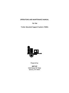
3 The Operation and MAINTENANCE MANUAL for the Environmental Control Unit (ECU) provided as Appendix E; and the Spares Listing provided as Appendix F. EQUIPMENT DESCRIPTION: The Trailer System consists of one 35kW 120/208-Volts AC, 3-phase, 60-Hz, Diesel Engine Generator (DEG), one 96,000 BTU/Hour Environmental Control Unit (ECU), insulated air ducts and one two-stage Load Bank and is designed to transport rapidly deployable shelters. The trailer is used in conjunction with the High Mobility Multi-purpose Wheeled Vehicle (HMMWV) M-1097, M-1113, M1123, and Tracked Personnel Carrier M-577.
4 The trailer is designed to a GVWR of 5,500 pounds. When fully loaded with cargo does not exceed 4,200 pounds to meet the towing and braking restrictions of the HMMWV. Tongue weight is less than 420 pounds with a full cargo complement. The trailer system meets the Military Transportation Management (MTMC) standard for internal/external airlift and accommodates load ramp departure angles to prevent damage to the vehicle, aircraft or tarmac in accordance with the requirements of DH-1-11, Design Note DN 5A2. The Trailer System is roll-on/roll-off capable for internal transport by C-5, C-17, C-130 or C-141 aircraft and two-point helicopter external lift by CH-47 and CH-53 without spreader bar.
5 MAJOR COMPONENTS Trailer: The trailer consists of a five-inch structural steel channel frame with aluminum fenders and bed. It is equipped with air and sea-lift / tie-down rings, a 3-inch pintel hook lunette eye, a hydraulic surge brake rated at 7,500 pounds and safety chains. The trailer is equipped with two hand operated parking brakes, 37 x Load Rating D radial tires and a 5,000 pound rated axle with an axle width to track with the HMMWV ( inches). The trailer is fitted with two MS52125-2 (24 VDC) tail light assemblies and connected via a neoprene jacketed cable to a terminal block in a HDT Global 3 TM-2003850F This document contains information proprietary to HDT Global.
6 Disclosure of this information is not permitted without the express consent of HDT Global. watertight junction box located at the trailer tongue and then via a neoprene jacketed cable to the MS75020, 12-pin plug for connecting to the HMMWV receptacle. The trailer incorporates an in-chassis 55-gallon aluminum fuel tank, fitted with a four-inch diameter filler and a mechanical, magnetically coupled fuel level gauge with a dial indicator located in a containment box at the tongue of the trailer to allow fueling without removal of cargo.
7 Tarpaulin tie-down hooks are attached around the periphery of the trailer. Two adjustable leveling jacks are provided at the rear of the trailer. A front adjustable support jack is provided to raise and lower the lunette to pintle height. The trailer is 160 inches long, has an overall width of 86 inches, and an overall height of 75 inches. Note: A leveling bubble is located on the cross bar at the A frame of the trailer between the fuel filler and the surge brake. The trailer should be level when towing, setting up, running, and storing.
8 DEG: The 120/208 VAC, 60Hz, three phase, DEG uses a John Deere, Tier II, three cylinder, turbocharged, liquid cooled, 1800 RPM diesel engine coupled to a single bearing, four pole Marathon Electric generator. The DEG is rated at 35kW continuous operation at the combined worst-case environment of 50C degrees (122F) and 10,000-foot altitude. The DEG is housed in a weatherproof, acoustically treated, aluminum enclosure with removable access doors. The enclosure includes the Instrumentation Panel protected by an observation door with window, a Barrier for mounting control components, a Circuit Breaker Panel, and a Power Panel for connection to the system load.
9 Instrument Panel: AC instrumentation includes an Ammeter, Voltmeter, Frequency Meter and Wattmeter. The engine instrumentation gauges include an Engine Battery Monitor, Oil Pressure Gauge, a Coolant Temperature Gauge, an Hour Meter, and a fuel gauge. Control switches include a combination AC Ammeter/Voltmeter four-position switch, a Synchronizing Switch, the Engine Select Switch OFF/RUN/START, a Panel Illumination Light Switch, an ECU Mode Select Switch, an ECU Thermostat, an ECU ON/OFF Switch. The Instrument Panel also incorporates a voltage adjust potentiometer, a speed control potentiometer, and an In-Synch indicator LED.
10 Automatic shut-off for Low Oil Pressure, Overspeed, High Coolant Temperature, and Reverse Power are incorporated into the design along with alarm indicators. The AC instrumentation provides indications of power in either the Shore Power or Generator Power modes of operation. Barrier: The Barrier contains mounted control components, relays, fuses, current transformers, governor controller, speed switch, terminal blocks, transducers and associated wiring. It is located behind the Instrument Panel and is accessed by HDT Global 4 TM-2003850F This document contains information proprietary to HDT Global.