Transcription of Optical Image Stabilization (OIS) - rohm.com
1 Innovations EmbeddedOptical Image Stabilization (OIS)White Paper2 Optical Image Stabilization (OIS) White PaperIntroductionWhether capturing still images or recording moving video, Image Stabilization will always be a major factor in reproducing a near perfect digital replica. A lack thereof will result in Image distortion through pixel blurring and the creation of unwanted artifacts. While media capturing devices such as digital cameras, digital camcorders, mobile phones, and tablets have decreased in physical size, their requirements for pixel count density and resolution quality have increased drastically over the last decade and will continue to rise. The market shift to compact mobile devices with high megapixel capturing ability has created a demand for advanced Stabilization techniques.
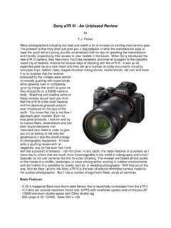
2 Two methods, electronic Image Stabilization (EIS) and Optical Image Stabilization (OIS), are the most common implementations. SLR CameraSmartphonePoint & Shoot CameraMirrorless CameraOIS Target MarketHighLowNowFuture10 MpixelResolutionTimelineFigure 1. Optical Image Stabilization Target Market3 Optical Image Stabilization (OIS) White PaperYawYawPitchPitchRollRollframes to reduce the sense of motion. Though the advantage with this method is the ability to create inexpensive and compact solutions, the resulting Image quality will always be reduced due to Image scaling and Image signal post-processing artifacts, and more power will be required for taking additional Image captures and for the resulting Image processing.
3 EIS systems also suffer when at full electronic zoom (long field-of-view) and under low-light conditions. Image Stabilization PrinciplesImage Stabilization is used to reduce blurring associated with motion and/or shaking of the camera during the time the Image sensor is exposed to the capturing environment. However, it does not prevent motion blur caused by movement of the target subject or extreme movements of the camera itself, only the relatively small shaking of the camera lens by the user within a few Optical degrees. This camera-user movement can be characterized by its pan and tilt components, where the angular movements are known as yaw and pitch, respectively.
4 Camera roll cannot be compensated since 'rolling' the lens doesn't actually change/compensate for the roll motion, and therefore does not have any effect on the Image itself, relative to the Image is a digital Image compensation technique which uses complex algorithms to compare frame contrast and pixel location for each changing frame. Pixels on the Image border provide the buffer needed for motion compensation. An EIS algorithm calculates the subtle differences between each frame and then the results are used to interpolate new Figure 2. Axes of Motion4 Optical Image Stabilization (OIS) White PaperOIS BehaviorOIS is a mechanical technique used in imaging devices to stabilize the recording Image by controlling the Optical path to the Image sensor.
5 The two main methods of OIS in compact camera modules are implemented by either moving the position of the lens (lens shift) or the module itself (module tilt).Camera movements by the user can cause misalignment of the Optical path between the focusing lens and center of the Image sensor. In an OIS system using the lens shift method, only the lens within the camera module is controlled and used to realign the Optical path to the center of the Image sensor. In contrast, the module tilt method controls the movement of the entire module, including the fixed lens and Image sensor. Module tilt allows for a greater range of movement compensation by the OIS system, with the largest tradeoff being increased module height.
6 Minimal Image distortion is also achieved with module tilt due to the fixed focal length between the lens and Image sensor. Overall, in comparison to EIS, OIS systems reduce Image blurring without significantly sacrificing Image quality, especially for low-light and long-range Image capture. However, due to the addition of actuators and the need for power driving sources compared to no additional hardware with EIS, OIS modules tend to be larger and as a result are more expensive to ZoomFigure 3. OIS and EIS Image Quality Comparison5 Optical Image Stabilization (OIS) White PaperMovement DirectionLens Shift MethodLens within the module is movedMovement DirectionModule Tilt MethodEntire camera module is movedHall SensorMagnetImage SensorLensImage SensorLensPhotoreflectorOIS Module ComponentsAn OIS system relies on a complete module of sensing, compensation, and control components to accurately correct for unwanted camera movement.
7 This movement or vibration is characterized in the X/Y-plane, with yaw/pan and pitch/tilt movements detected by different types of isolated sensors. The lens shift method uses Hall sensors for lens movement detection while the module tilt method uses photoreflectors to detect module movement. Both methods require a gyroscope in order to detect human movement. ROHM s OIS controllers use gyroscope data within a lens target positioning circuit to predict where the lens needs to return in order to compensate for the user's natural movement. With lens shift, Hall sensors are used to detect real-time X/Y locations of the lens after taking into consideration actuator mechanical variances and the influence of gravity.
8 The controller uses a separate internal servo system that combines the lens positioning data of the Hall sensors with the target lens position calculation from the gyroscope to calculate the exact driving power needed for the actuator to reposition the lens. With module tilt, the process is similar but the module s location is measured and repositioned instead of just the lens. With both methods, the new lens position realigns the Optical path to the center of the Image 4. Main Methods of OIS Compensation6 Optical Image Stabilization (OIS) White PaperStatic AlignmentImagesensorLens for OISO ptimalopticalpathLight ofsubjectPhone MovementWith OIS SystemLens movement is compensated by the OIS controller and the Optical path is correctedAWithout OIS SystemThe difference between A & B causes Image degradationABFigure 5.
9 Lens Shift OIS Principle7 Optical Image Stabilization (OIS) White PaperOIS System ControlOIS control is designed to be very simple from the customer s standpoint, consisting of simply ON/OFF and enable/power-save modes. The only other commands are either optional manual control of the lens in the X/Y plane or changing the OIS performance based on ambient conditions such as day, night, sports, picture, video, or viewfinder. This allows for minimal I2C traffic from the host application processor to the OIS controller and simplifies software driver development for the end customer. All of the actual OIS control algorithms are performed autonomously on the controller itself, using the internal processor and RAM for the 's OIS ArchitectureROHM offers two OIS controller architectures, including a fully programmable ARM Cortex-M0 processor with custom programmable digital signal processing for 'gyroscope signal processing' and 'servo control', as well as ROHM s custom, fully programmable RMCU processor with integrated programmable 'gyroscope signal processing' and 'servo control'.
10 All of the OIS work memory and control calculations are performed on the OIS controller ApplicationProcessorImageSensorOISC ontrollerOISG yroscopeMIPI / MIDIP ower-SaveSPII2 CLens(AutofocusOptional)X-AxisHallSensor X-AxisOISA ctuatorY-AxisHallSensorY-AxisOISA ctuatorFigure 6. General OIS Block Diagram8 Optical Image Stabilization (OIS) White PaperPower Down ModeLens Position:FloatingInitialize (OIS OFF)Lens Position:Stable (fixed position)OIS Mode SettingPicture / Movie / ViewfinderDay / Night / SportOIS ONOIS driver auto-controlManual Control(Optional)Host processorcontrolledMode selection available via I2C commandsFigure 7. Standard OIS Operation Modes9 Optical Image Stabilization (OIS) White Paperitself without the need for the external host processor s computational power or external memory for storing calculation variables.