Transcription of Optics - Opto Engineering
1 Basic purpose of a lens of any kind is to collect the light scattered by an object and recreate an image of the object on a light-sensitive sensor (usually CCD or CMOS based). A certain number of parameters must be considered when choosing Optics , depending on the area that must be imaged (field of view), the thickness of the object or features of interest (depth of field), the lens to object distance (working distance), the intensity of light, the Optics type (telecentric/entocentric/pericentric), following list includes the fundamental parameters that must be evaluated in Optics Field of View (FoV): total area that can be viewed by the lens and imaged onto the camera sensor .
2 Working distance (WD): object to lens distance where the image is at its sharpest focus. Depth of Field (DoF): maximum range where the object appears to be in acceptable focus. sensor size : size of the camera sensor s active area. This can be easily calculated by multiplying the pixel size by the sensor resolution (number of active pixels in the x and y direction). Magnification: ratio between sensor size and FoV. Resolution: minimum distance between two points that can still be distinguished as separate points. Resolution is a complex parameter, which depends primarily on the lens and camera basicsLens approximations and equationsThe main features of most optical systems can be calculated with a few parameters, provided that some approximation is accepted.
3 The paraxial approximation requires that only rays entering the optical system at small angles with respect to the optical axis are taken into account. The thin lens approximation requires the lens thickness to be considerably smaller than the radii of curvature Fig. 1: Basic parameters of an optical 2: C-mount mechanical layoutFig. 3: CS-mount mechanical layoutCamera mountsDifferent mechanical mounting systems are used to connect a lens to a camera, ensuring both good focus and image stability. The mount is defined by the mechanical depth of the mechanics (flange focal distance), along with its diameter and thread pitch (if present). It s important that the lens flange focal distance and the camera mount flange distance are exactly the same, or focusing issues may arise.
4 The presence of a threaded mechanism allows some adjustment to the back focal distance, if needed. For example, in the Opto Engineering PCHI series lenses, the backfocal adjustment is needed to adjust the focus for a different field of is the most common Optics mount in the industrial market. It is defined by a flange focal distance of mm, a diameter of 1 ( mm) with 32 threads per inch. CS-mount is a less popular and 5 mm shorter version of the Cmount, with a flange focal distance of mm. A CS-mount camera presents various issues when used together with C-mount Optics , especially if the latter is designed to work at a precise back focal h hof the lens surfaces: it is thus possible to ignore optical effects due to the real thickness of the lenses and to simplify ray tracing calculations.
5 Furthermore, assuming that both object and image space are in the same medium ( air), we get the fundamental equation:1/s 1/s = 1/fwhere s (s ) is the object (image) position with respect to the lens, customarily designated by a negative (positive) value, and f is the focal length of the optical system (cf. Fig. 1). The distance from the object to the front lens is called working distance, while the distance from the rear lens to the sensor is called back focal distance. Henceforth, we will be presenting some useful concepts and formulas based on this simplified model, unless otherwise stated. Sensor1 x 32 mmC-mountSensor1 x 32 mmCS-mountWorking distanceVOpticsFig.
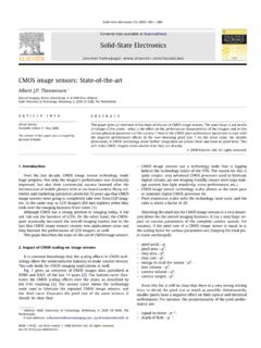
6 4: F-mount mechanical layoutFig. 7: Common area scan sensors formatFig. 8: Area scan sensors relative sizesFig. 6: Common line scan sensors formatsFig. 5: Mxx mount mechanical layoutsF-mount is a bayonet-style mount originally developed by Nikon for its 35 mm format cameras, and is still found in most of its digital SLR cameras. It is commonly used with bigger sensors, full-frame or line-scan cameras. Lenses can be easily swapped out thanks to the bayonet mount, but no back focal adjustment is are different types of camera mounts defined by their diameter ( M72, M42), thread pitch ( 1 mm, mm) and flange focal distance. They are a common alternative to the F-mount for larger mm44 mmF-mountSensorM42undefinedT-mount (T1 = ; T2 = M42 x ) sensor typeDiagonalWidthHeight(mm)(mm)(mm)1/3 frame - 35 px x 10 m2048 px x 14 m4096 px x 7 m4096 px x 10 m7450 px x m6144 px x 7 m8192 px x 7 m12288 px x 5 mm35 mm41 mm43 mm62 mmEach camera mount is more commonly used with certain camera sensor formats.
7 The most typical sensor formats are listed below. It is important to remember that these are not absolute values two cameras listed with the same sensor format may differ substantially from one another in terms of aspect ratio (even if they have the same sensor diagonal). For example, the Sony Pregius IMX250 sensor is listed as 2/3 and has an active area of mm x mm. The CMOSIS CMV2000 sensor is also listed as 2/3 format but has an active area of mm x x (M58 x ) SensorundefinedM72 x (M72 x )SensorFull frame - 35 mm1/314/31 LengthMagnification and field of viewThe focal length of an optical system is a measure of how strongly the system converges or diverges rays of light.
8 For common optical systems, it is the distance over which collimated rays coming from infinity converge to a point. If collimated rays converge to a physical point, the lens is said to be positive (convex), whereas if rays diverge the focus point is virtual and the lens is said to be negative (concave cf. Fig. 9). All Optics used in machine vision application are overall positive, they focus incoming light onto the sensor magnification M of an Optics describes the ratio between image (h ) and object size (h):M = h /hA useful relationship between working distance (s), magnification (M) and focal length ( f ) is the following:s = f (M-1)/MMacro and telecentric lenses are designed to work at a distance comparable to their focal length (finite conjugates), while fixed focal length lenses are designed to image objects located at a much greater distance than their focal length (infinite Fig.)
9 9: Positive (left) and negative (right) lensf = 8 mmFig. 10: Focal length and field of viewFig. 11: Given a fixed sensor size , if magnification is increased the field of view decreases and viceversaf = 25 mmf = 50 mmconjugates). It is thus convenient to classify the first group by their magnification, which makes it easier to choose the proper lens given the sensor and object size , and the latter by their focal length. Since fixed focal length lenses also follow the previous equation, it is possible to calculate the required focal length given the magnification and working distance, or the required working distance given the sensor size , field of view and focal length, etc.
10 (some examples are given at the end of this section). For macro and telecentric lenses instead, the working distance and magnification are typically focal length adjustmentMany cameras are found not to respect the industrial standard for C-mount ( mm), which defines the flange-to-detector distance (flange focal length). Besides all the issues involved with mechanical inaccuracy, many manufacturers don t take into the due account the thickness of the detector s protection glass which, no matter how thin, is still part of the actual flange to detector is why a spacer kit is supplied with Opto Engineering telecentric lenses including instructions on how to tune the back focal length at the optimal optical systems used in machine vision, in which rays reflected from a faraway object are focused onto the sensor plane, the focal length can be also seen as a measure of how much area is imaged on the sensor (Field of View).