Transcription of Optimizing Efficiency in HF Tube Welding Processes
1 Optimizing Efficiency in John Wright's 30-year career in high frequency tube Welding has spanned South Africa, the United Kingdom, and - for the last 22 years - the United HF Tube Welding Processes States. He founded Electronic Heating Equipment in Buckley, Washington, in 1980. The company manufactures impeders & work coils for induction By: John Wright, Electronic Heating Equipment, Inc. - USA tube Welding , & provides technical support for all types of high frequency tube Welding equipment. Modern solid state welders can convert 60Hz power to the high frequencies voltage causes a current to flow along the edges to the point where they meet, used for Welding at efficiencies of 90%, compared to a maximum 65% for causing rapid heating of the metal. Pressure is applied by the weld rolls, which the older vacuum tube equipment. At the very best, improvements in welder forces the heated metal into contact, forming a hot diffusion bond. This design may raise this figure by another 5% or so.
2 In contrast, the process pressure forces molten metal and any impurities out of the weldment, so the Efficiency is typically less than 20%, so this is where some worthwhile resulting structure is that of a forging, rather than the casting formed by improvement can be realized. most other Welding Processes , & it results in one of the strongest welded structures possible. If we calculate the amount of energy actually required to weld ( in.) thick steel edge to edge at 100 meters per minute (325 fpm), it works out The only real difference between high frequency contact & induction Welding to less than 20 kW., however anyone familiar with induction Welding knows is that with contact Welding , the voltage is applied directly to the strip edges that at least 100 kW. of HF weld power is normally required. 4/5 of the by means of sliding contacts, whereas in the case of induction Welding , the power generated by the welder is wasted in heating parts of the tube other voltage is induced by the magnetic flux surrounding the coil.
3 Both methods than the desired heat affected zone, and in waste heat developed in the coil, have their advantages & drawbacks, but in general, induction Welding will the impeder, the weld rolls & the mill structure itself. The key to minimizing produce smoother, more consistent welds but at slightly lower Efficiency . this power loss is to use proper setup of the coil, impeder & the tube mill itself. Why Choose a High Frequency? High frequency tube Welding is one of the most forgiving industrial Processes , If we were to apply 60 Hz. power to a pair of contacts positioned as shown in & it is possible to produce acceptable tubing for most purposes even with a fig 1a, most of the current would simply flow around the back of the tube, hopelessly incorrect setup! The main incentive for proper setup of the welder heating the entire tube. Current will always take the path of lowest impedance is the amount of money that can be saved in electricity costs.
4 Based on power (not necessarily resistance!). With DC & low frequency AC, resistance &. costing 10 cents per kilowatt hour, a 400 kW welder operating 60 hours a impedance are pretty much the same thing. Technically speaking, at low week consumes $125, in electrical power each year. In many cases, frequencies, the impedance is dominated by its resistive component. As the power consumption can be reduced by 50% just by Optimizing the Welding frequency is raised, the magnetic fields resulting from the current flow start process, saving tens of thousands of dollars a year. This kind of fine tuning to affect its behavior, and inductive reactance becomes the dominant factor usually improves product quality, reduces downtime & increases yield as well. in determining impedance. Both the current path along the edges of the strip to the apex, and the parasitic path around the circumference of the tube behave as inductors, & their inductive reactance increases with frequency, however the effect of frequency is much more pronounced on the circumferential current path.
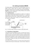
5 Another reason for using a higher frequency is that in the case of induction Welding , it is desirable to keep the size of the coil reasonably small. The coil & the tube form a transformer, with the coil being the primary winding, &. the tube being a single turn secondary. The amount of power that can be coupled through a transformer depends on the strength of the magnetic flux, and the rate at which it changes (frequency). The higher the frequency, the less flux is required. This results in a coil with less turns & lower current. If it were possible to weld tubing at 60 Hz. power line frequencies, it would require a coil having hundreds of turns, carrying thousands of amps. A typical HF. Welding coil has 1 - 3 turns & carries a few hundred amps of current. The higher frequencies also affect the behavior of the current that flows in Figure 1. the vee . As frequency is increased, the current tends to concentrate closer HF Welding theory & closer to the edges of the strip.
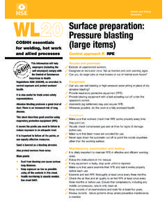
6 This is partly due to the skin effect (fig. 2). which causes current to flow on the surface of conductors at high frequency, HIGH FREQUENCY Welding is a form of electrical resistance Welding and partly due to the proximity effect (fig. 3) which causes current on (ERW). A voltage is applied (HF contact) or induced (HF induction) across adjacent conductors to concentrate on the adjacent surfaces. Both of these the edges of the open tube just prior to the point of closure (see fig. 1). This effects are caused by distortion or interaction between the magnetic fields TUBE & PIPE TECHNOLOGY - November/December 1999. Figure 2 Figure 3. associated with the current flow. The combined skin and proximity effects Shortening the vee and keeping it narrow reduce its impedance. A longer vee result in less metal being heated, using less current, which translates into also provides more time for heat to conduct away from the edges, so higher Efficiency . conduction losses increase as well.
7 It is important to realize that vee length has more effect on the heat affected zone width than welder frequency! Frequencies used for tube Welding range from roughly 100kHz to 800kHz., with lower frequencies being used for large, heavy wall tube, and the upper Shortening the work coil & increasing the tube diameter both increase the range being used for small, thin walled products, especially those using non- impedance of the tube The impedance can be further increased by ferrous material. placing an impeder in the tube. Under ideal circumstances, this impedance is raised to a point where most of the current flows in the vee, but this is not Efficient welder operation possible with small tube diameters because of the limited space available for the impeder. The introduction of scarfing equipment also takes up space The primary cause of low Efficiency is incorrect coil & impeder position. that might otherwise be available for ferrite. When a voltage is applied (or induced) across the strip edges, current will flow in two main paths.
8 The current that flows along the edges of the strip to Edge presentation the apex of the vee heats the strip to Welding temperature. Current will also tend to flow around the inside circumference of the open tube. This heats If the strip edges are not presented in a parallel fashion, or if they have burrs the entire tube, and does not contribute to the Welding process. With induction or irregularities that have not been completely planished in the fin passes, Welding , the sum of these two currents also flows on the outside surface of Efficiency will suffer because a larger mass of metal must be heated before a the tube, as this is the return path that completes the circuit. Note that any wall-to-wall weld can occur. Bad edge condition also results in excessive current that flows on the inside surface also returns on the outer surface, squeeze out of molten material, causing a large & often irregular weld bead resulting in twice the power loss!
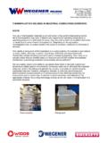
9 Power is proportional to the square of current, which must be trimmed off. Such a condition nearly always results in weld so a small increase in current results in a large increase in power. defects as well. The amount of current that flows along the vee & around the inside circumference depends on the impedance of these two paths (fig. 4). Figure 5. A common condition is that where the inside corners of the strip meet before the outside corners, as illustrated in fig. 5a,b&c. This occurs because both top & bottom surfaces of the strip had the same width when it was flat, and Figure 4 when it is formed into a tube, the inside surface must be compressed and/or TUBE & PIPE TECHNOLOGY - November/December 1999. the outside surface stretched in order for the edges to become parallel. Usually diameter & a height equal to the measured distance provides the approach both stretching & compression occur, & most of this takes place in the fin angle. For a 3mm drill that stops 45mm from the apex, the angle is equal to passes.
10 If these rolls are worn, or improperly set, edge presentation will not 90 - (tan-1 45/3), or . be correct. When the inside corners meet first, most of the current will flow along these corners because the vee length is shortened. This causes excessive heating & melting, which in turn produces a large & usually ragged inside bead. In order to get a weld that extends through the entire thickness of the tube to the outside surface, a much greater amount of weld power is needed. Fig. 5d,e & f show the correct, parallel presentation of the edges & the resulting weld formation. Roll design for proper edge presentation is beyond the scope of this article, however any roll manufacturer can provide assistance in this area. Vee length & angle From a pure Efficiency standpoint, the vee should be as short as physically possible, in order to reduce conduction losses, and to direct the majority of the induced current to flow in the vee. In practice, there are several other factors that must be considered.