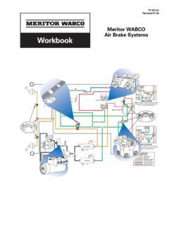
Transcription of or Anti-Lock Braking System Training Program Revised 3-99 ...
1 Anti-LockBraking System Training ProgramStudent ManualTP-9738 Revised 3-99$ 1 ABS Components and System OperationModule 2 ABS Diagnosis and RepairModule 3 ATC Operation, Diagnosis and RepairTractor 1 ABS Components and System Operation1-1 Table of ContentsDefinition of Terms .. 2 ABS System Overview and Components .. 3 System Operation.. 171-2 Module 1 ABS Components and System OperationDefinition of TermsABS Configuration Their are three available ABS configurations. The configuration name is based on the number of modulator valves and sensors on the vehicle. The three configurations are 4S/4M, 6S/4M and 6S/6M (S = Sensors and M = ABS Modulator valves).
2 ABS Modulator Valve Electropneumatic control valve that contains the solenoids used for controlling air pressure. They can precisely modulate air pressure during an ABS-controlled brake Control Unit (ECU) The ECU contains the computers that take the input signals, processes the information and then sends output signals to the necessary components. The ECU controls the Anti-Lock brake and automatic traction control systems, as well as the diagnostic A device that converts an electrical signal into mechanical movement. It consists of a coil with a moveable core that changes positions by means of electromagnetism when current flows through the Wheel A metal ring, normally with 100 evenly spaced teeth.
3 The tooth wheel could have 80 or 120 teeth, based on extremely small or extremely large tires. It is usually attached to the barrel of the hub on each ABS-monitored wheel. When the wheel rotates, the teeth move past the wheel speed sensor to create an electrical signal that the ECU uses to determine wheel Speed Sensor A magnetic pickup-type sensor positioned near a wheel that produces a signal to indicate wheel speed to the ECU. In general, a sensor generates an electrical signal with a frequency proportional to the wheel speed. A permanent magnet and passing metal teeth combine to produce a signal. The teeth alter the magnetic field produced by the sensor.
4 The changing magnetic field produces AC voltages in pickup coils within the sensor. In ABS applications, these signals are relayed to the ECU, which processes them to determine wheel ABS A System that has four sensors and four ABS modulator valves (4S/4M). The System may also have six sensors and four ABS modulator valves (6S/4M).Six-Channel ABS A System that has six sensors and six ABS modulator valves (6S/6M).ABS System Overview and Components1-3 Table of ContentsSection Overview .. 4 Anti-Lock Braking System (ABS) Overview .. 5 ABS Overview .. 5 ABS Operation Summary .. 5 ABS Features and Benefits .. 6 ABS Components.
5 7 Wheel-Speed Sensing System Components .. 7 Tooth Wheel .. 7 Wheel Speed Sensor .. 8 Sensor Holder and Spring Clip .. 8 Sensor Extension Cable .. 8 Electronic Control Unit (ECU) .. 9 ECU Types .. 9 ABS Modulator Valve.. 11 Vehicle Wheel/ABS Configurations .. 13 ABS Indicator Lamp .. 13 Blink Code Switch .. 13J-1587 Diagnostic Connector .. 13 Section Summary .. 15 Progress Check 1-1 .. 161-4 ABS System Overview and ComponentsSection OverviewThis section introduces the basics of the Meritor WABCO Anti-Lock Braking System with D-version electronic control unit. It also discusses specific features and benefits of the Meritor WABCO completing this section, the technician will be able to:rDescribe the basic functions of the Meritor WABCO ABS indicator the ABS features that can aid in diagnostics and wheel speed sensors, ABS valves and ABS the ECU and describe how it communicates with other the different ABS : View video tape segment number one.
6 Return to this workbook when instructed to by the video tape and read the rest of Module System Overview and Components1-5 Anti-Lock Braking System (ABS) OVERVIEWABS OverviewThe Anti-Lock Braking System modulates the air pressure in the brake chambers to prevent wheel lockup and provide precise Braking control during over- Braking . This enhances:rVehicle stabilityrSteerability under emergency Braking rStable stopping on icy or rain-slicked road surfaces and in curvesrStopping distanceABS also reduces the possibility of:rJackknifing or plowout (loss of steering control)rTire flatspottingABS Operation SummaryABS takes over control of the air pressure whenever a wheel starts to lock up.
7 Sensors continuously monitor wheel speed and send this information to an Electronic Control Unit (ECU). When a wheel starts to lock, the ECU, using the wheel-speed information and programmed data, sends output signals to control the operation of the ABS valves. The ECU causes the ABS valves to adjust air pressure supplied to the brake chambers to control Braking and prevent wheel System Overview and ComponentsABS Features and BenefitsFeaturesBenefitsIndividual control of steering and drive wheelsIncreased stability and driver control reduces possibility of jackknifing and keeps steering systemIf System malfunctions, ABS is shut off at the affected wheel end(s), returning affected wheel(s) to normal traction control (optional)
8 Controls excessive wheel spin during diagnostic System Built-in System makes maintenance checks quick and tool compatibilityCan use industry-standard electronic diagnostic tools. Pro-Link 9000 diagnostic tool has a cartridge designed specifically for Meritor WABCO ABS/ATC code switchStandard switch allows access to fault codes without the use of a diagnostic indicator lampInforms vehicle operator that an ABS fault has been detected. The lamp is also used for displaying diagnostic blink codes on D version System Overview and Components1-7 ABS COMPONENTSW heel-Speed Sensing System ComponentsThe ECU uses input from the wheel-speed sensing System to determine when to activate ABS and ATC operation.
9 The following components comprise the System :rTooth wheelrWheel speed sensorrSensor holder and spring cliprSensor extension cableTooth WheelThe tooth wheel normally has 100 evenly spaced teeth and is usually mounted to the barrel of the hub on each sensed o t h W h e e l1-8 ABS System Overview and ComponentsWheel Speed SensorFor optimum performance, the pencil-type wheel speed sensor is a completely sealed unit and is located in the wheel end. A vehicle will normally have four sensors. The sensors are usually mounted in the flange of the steering knuckles at each side of the steering axle. Additional sensors are located in sensor holders attached to the drive axle housing on one of the two tandem axles.
10 Sensor mounting location depends on the type of suspension. Typically, on a vehicle with a spring suspension, the sensors are mounted on the forward tandem axle. On a vehicle with an air suspension, the sensors are mounted on the rear tandem axle. A 6S/6M and a 6S/4M System will have two additional sensors at the second rear axle. Two sensor types are available: a right-angle sensor and a straight sensor. The type used depends on the vehicle make and Speed SensorsSensor Holder and Spring ClipOn rear wheels, the sensor is mounted in sensor holders that are welded to the axle housing. A spring clip grips the sensor into the holder.