Transcription of ORIGINAL INSTRUCTIONS IE101M ... - Industrial Compressor
1 Model 491-107 Installation, Operation & Maintenance ManualPlain Style Compressors for Liquid Transfer-Vapor RecoveryORIGINAL INSTRUCTIONS IE101 MWarning: (1) Periodic inspection and maintenance of Corken products is essential. (2) Inspection, maintenance and installation of Corken products must be made only by experienced, trained and qualified personnel. (3) Maintenance, use and installation of Corken products must comply with Corken INSTRUCTIONS , applicable laws and safety standards. (4) Transfer of toxic, dangerous, flammable or explosive substances using Corken products is at user s risk and equipment should be operated only by qualified personnel according to applicable laws and safety beyond , use and maintain this equipment according to Corken s INSTRUCTIONS and all applicable federal, state, local laws and codes. Periodic inspection and maintenance is One Year WarrantyCORKEN, INC.
2 Warrants that its products will be free from defects in material and workmanship for a period of one year from date of installation, provided that the warranty shall not extend beyond twenty-four (24) months from the date of shipment from CORKEN. If a warranty dispute occurs, the DISTRIBUTOR may be required to provide CORKEN with proof of date of sale. The minimum requirement would be a copy of the DISTRIBUTOR S invoice to the products which fail within the warrant period due to defects in material or workmanship will be repaired or replaced at CORKEN s option, when returned, freight prepaid to CORKEN, INC., 9201 North I-35 Service Road, Oklahoma City, OK. subject to wear or abuse, such as mechanical seals, blades, piston rings, valves and packing, and other parts showing signs of abuse, neglect or failure to be properly maintained are not covered by this limited warranty.
3 Also, equipment, parts and accessories not manufactured by CORKEN but furnished with CORKEN products are not covered by this limited warranty and the purchaser must look to the ORIGINAL manufacturer s warranty, if any. This limited warranty is void if the CORKEN product has been altered or repaired without the consent of implied warranties, including any implied warranty of merchantability or fitness for a particular purpose, are expressly negated to the extent permitted by law and shall in no event extend beyond the expressed warrantee DISCLAIMS ANY LIABILITY FOR CONSEQUENTIAL DAMAGES DUE TO BREACH OF ANY WRITTEN OR IMPLIED WARRANTY ON CORKEN PRODUCTS. Transfer of toxic, dangerous, flammable or explosive substances using CORKEN products is at the user s risk. Experienced, trained personnel in compliance with governmental and Industrial safety standards should handle such notes relating to the European Union (EU) Machinery DirectiveCompressors delivered without electric motors are not considered as machines in the EU Machinery Directive.
4 To ensure EU compliance, the Compressor should be ordered with the optional 3022-1X Declaration of Conformity. The fabricator of the machinery must assure and declare full compliance with this Directive before the machine in which the Compressor will be incorporated, or of which it is a part, is put into the FactoryBefore contacting the factory, note the model and serial numbers. The serial number directs Corken personnel to a file containing all information on material specifications and test data applying to the product. When ordering parts, the Corken service manual or Installation, Operations, and Maintenance (IOM) manual should be consulted for the proper part numbers. ALWAYS INCLUDE THE MODEL NUMBER AND SERIAL NUMBER WHEN ORDERING model and serial numbers are shown on the nameplate of the unit. Record this information for future No. Serial Purchased Date InstalledPurchased From Installed By2 Table of ContentsChapter 1 Introduction.
5 Liquid Transfer By Vapor Differential Pressure .. Residual Vapor Recovery .. Compressor Construction Features ..6 Chapter 2 Installing Your Corken Compressor .. Location .. Foundation .. Piping .. Liquid Traps .. Driver Installation / Flywheels .. Crankcase Lubrication .. Relief Valves .. Truck Mounted Compressors .. Shutdown/Alarm Devices ..15 Chapter 3 Starting Up Your Corken Compressor .. Inspection After Extended Storage .. Flywheel and V-belt Alignment .. Crankcase Oil Pressure Adjustment .. Startup Check List ..17 Chapter 4 Routine Maintenance Chart ..18 Chapter 5 Routine Service and Repair Procedures ..185 .1 Va l ve s .. Heads .. Piston Rings and Piston Ring Expanders .. Pistons .. Piston Rod Packing Adjustment .. Cylinder and Packing Replacement .. Bearing Replacement for Crankcase and Connecting Rod .. Wrist Pin Bushing Replacement .. Replacing Connecting Rod Bearings.
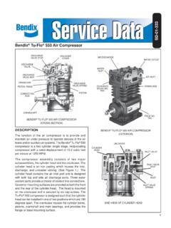
6 Replacing Crankcase Roller Bearings .. Oil Pump Inspection ..26 Chapter 6 Extended Storage Procedures .. Repair Kits .. Gasket Sets ..28 AppendicesA. Model Number Identification Code and Available Options ..30B. Specifications ..32C. Compressor Selection ..38D. Outline Dimensions ..42E. Parts Details ..58 Model 91 and F91 ..58 Model 291 and F291 ..66 Model 491 and F491 ..74 Model 691 and F691 ..82 Model D891 and FD891 ..90F. Troubleshooting ..983 Connections:Available in threaded NPT or Class 300 RF valves:Valves are quiet and highly durable. Special suction valves tolerating small amounts of condensate are seals:Easy to install O-ring seals head and iron construction:Cylinder and head are made of ductile iron for maximum thermal shock PTFE piston rings:State-of-the-art piston ring designs to provide the most cost-effective operation of compressors for non-lube service.
7 The step-cut design provides higher efficiencies during the entire life of the piston locked piston:Simple piston design allows end clearance to be precisely set to provide maximum efficiency and long rod seals:Seals constructed of PTFE incorporating special fillers to maximize leakage control. Spring loaded seal design self adjusts to compensate for normal 1 coated piston rods:Impregnated nitride coating provides superior corrosion and wear crosshead:Durable cast-iron crossheads provide superior resistance to corrosion and crankcase with filter:Self-reversing oil pump ensures proper lubrication regardless of directional rotation to main and connecting rod bearings. Standard 10-micron filter ensures long-lasting bearing life (not available on Model 91).1 Registered trademark of TTI Group 1 IntroductionConstruction Details Model F291 Compressor41.
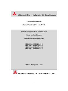
8 1 Liquid Transfer By Vapor Differential PressureCorken LPG/NH3 compressors are designed to transfer liquefied gases such as butane/propane mixtures (liquefied petroleum gas or LPG) and Anhydrous Ammonia (NH3) from one tank to another. Liquefied gases such as LPG and NH3 are stored in closed containers where both the liquid and vapor phases are : Typical nameplate (also serves as the packing adjusting screw cover)There is a piping connection between the vapor sections of the storage tank and the tank being unloaded, and there is a similar connection between the liquid sections of the two tanks. If the connections are opened, the liquid will seek its own level and then flow will stop; however, by creating a pressure in the tank being unloaded which is high enough to overcome pipe friction and any static elevation difference between the tanks, all the liquid will be forced into the storage tank (see figure ).
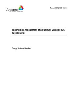
9 The gas Compressor accomplishes this by withdrawing vapors from the storage tank, compressing them and then discharging into the tank being unloaded. This procedure slightly decreases the storage tank pressure and increases the pressure in the other tank, thereby causing the liquid to process of compressing the gas also increases the temperature, which aids in increasing the pressure in the tank being .2 Residual Vapor RecoveryThe principle of residual vapor recovery is just the opposite of liquid transfer. After the liquid has been transferred, the four-way control valve (or alternate valve manifolding) is reversed so that the vapors are drawn from the tank just unloaded and discharged into the receiving tank. Always discharge the recovered vapors into the liquid section of the receiving tank . This will allow the hot, compressed vapors to condense, preventing an undesirable increase in tank pressure (see figure ).
10 Residual vapor recovery is an essential part of the value of a Compressor . There is an economical limit to the amount of vapors that should be recovered, the cost of operation equals the price of the product being recovered, the operation should be stopped. For most cases in LP-Gas and Anhydrous Ammonia services, this point is reached in the summer when the Compressor inlet pressure is 40 to 50 psig Figure : Liquid transfer by vapor differential reduces pressure in storage tank by removing vaporCompressor increases pressure in tank car by adding vaporPressure difference between tanks causes liquid to flow out of the tank car into the storage tankFour Way Valve Position 1 Vapor LineVapor LineLiquid Line5 Vapor is bubbled through liquid to help cool and recondense itRemoving vapor from tank causes liquid heel to boil into vaporLiquid line is valved closed during vapor Way Valve Position 2 Vapor LineVapor LineLiquid Line( to bars).