Transcription of Overcurrent Protection & Coordination for Industrial ...
1 Overcurrent Protection & Coordination for Industrial Applications Doug Durand, IEEE Continuing Education Seminar - Houston, TX November 3-4, 2015 Slide 2 Day 1 Introduction Using Log-Log Paper & TCCs Types of Fault Current Protective Devices & Characteristic Curves Coordination Time Intervals (CTIs) Effect of Fault Current Variations Multiple Source Buses Partial Differential Relaying Directional Overcurrent Coordination Day 2 Transformer Overcurrent Protection Motor Overcurrent Protection Conductor Overcurrent Protection Generator Overcurrent Protection Coordinating a System Coordination Quizzes Coordination Software References Agenda Introduction Slide 4 Protection Objectives Personnel Safety Slide 5 Protection Objectives Equipment Protection Slide 6 Protection Objectives Service Continuity & Selective Fault Isolation kV 480 V kV/480 V MVA Faults should be quickly detected and cleared with a minimum disruption of service.
2 Protective devices perform this function and must be adequately specified and coordinated. Errors in either specification or setting can cause nuisance outages. Slide 7 Types of Protection Distance High-Impedance Differential Current Differential Under/Overfrequency Under/Overvoltage Over Temperature Overload Overcurrent Protective devices can provide the following assortment of Protection , many of which can be coordinated. We ll focus primarily on the last one, Overcurrent . Slide 8 Coordinating Overcurrent Devices Tools of the trade in the good old Slide 9 Coordinating Overcurrent Devices Tools of the trade in the good old Slide 10 Coordinating Overcurrent Devices Tools of the trade in the good old Slide 11 Coordinating Overcurrent Devices Tools of the trade in the good old Slide 12 Coordinating Overcurrent Devices Old-world Slide 13 Coordinating Overcurrent Devices Tools of the trade Slide 14 Coordinating Overcurrent Devices New-world Using Log-Log Paper & TCCs Slide 16 1 10 100 1000 Time In Seconds 1 10 100` 1000 10000 Current in Amperes Time-Current Curve (TCC) Log-Log Plots Why log-log paper?
3 Log-Log scale compresses values to a more manageable range. I2t withstand curves plot as straight lines. effectively steady state 1 minute typical motor acceleration typical fault clearing 5 cycles (interrupting) 1 cycle (momentary) FLC = 1 pu Fs = pu Fp = 577 pu I2t withstand curves plot as straight lines Slide 17 1 10 100 1000 Time In Seconds 1 10 100` 1000 10000 Current in Amperes 5000 hp Motor TCC Plotting A Curve FLC = A LRC = A Accel. Time = 2 s kV 5000 hp 90% PF, 96% , A LRC, 2 s start M kV kV kV 10 MVA Slide 18 1 10 100 1000 Time In Seconds 1 10 100` 1000 10000 Current in Amperes 5000 hp Motor TCC with Fault on Motor Terminal Plotting Fault Current & Scale Adjustment FLC = A LRC = A Accel. Time = 2 s kV 5000 hp 90% PF, 96% , A LRC, 2 s start 15 kA 15 kA x 10 A M kV kV kV 10 MVA Slide 19 1 10 100 1000 Time In Seconds 1 10 100` 1000 10000 Current in Amperes 5000 hp Motor TCC with Fault on Transformer Primary Voltage Scales kV 5000 hp 90% PF, 96% , A LRC, 2 s start 15 kA kA x 10 A 45 kA = (45 x ) = kA @ kV 45 kA @ kV = ?
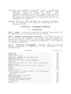
4 @ kV x 100 A @ kV 15 kA M kV kV kV 10 MVA Types of Fault Currents Slide 21 Fault Current Options ANSI Momentary Symmetrical Momentary Asymmetrical Momentary Crest Interrupting Symmetrical Adjusted Interrupting Symmetrical IEC Initial Symmetrical (Ik ) Peak (Ip) Breaking (Ib) Asymmetrical Breaking (Ib,asym) Momentary Current Crest/Peak Interrupting/Breaking Initial Symmetrical Slide 22 Fault Current Options Symmetrical currents are most appropriate. Momentary asymmetrical should be considered when setting instantaneous functions. Use of duties not strictly appropriate, but okay. Use of momentary/initial symmetrical currents lead to conservative CTIs. Use of interrupting currents will lead to lower, but still acceptable CTIs. Momentary Current Crest/Peak Interrupting/Breaking Initial Symmetrical Protective Devices & Characteristic Curves Slide 24 Electromechanical Relays (EM) 1 10 100 100 1 10 MULTIPLES OF PICK-UP SETTING TIME IN SECONDS Time Dial Settings 1 2 3 10 IFC 53 RELAY Very Inverse Time Time-Current Curves Slide 25 M kV kV 5000 hp FLC = A SF = IFC 53 800/5 Set AT = 4 Electromechanical Relays Pickup Calculation The relay should pick-up for current values above the motor FLC ( ~ 600 A).
5 For the IFC53 pictured, the available ampere-tap (AT) settings are , , , , 1, , , 2, , 3, & 4. For this type of relay, the primary pickup current was calculated as: PU = CT Ratio x AT PU = (800/5) x 3 = 480 A (too low) = (800/5) x 4 = 640 A (107%, okay) Slide 26 1 10 100 100 1 10 MULTIPLES OF PICK-UP SETTING TIME IN SECONDS M kV kV 5000 hp A, SF = 1 IFC 53 15 kA 800/5 Setting = 4 AT (640 A pickup) TD = ?? s s Time Dial 10 s s Time Dial 3 s s Time Dial 10000/640 = 15000/640 = Multiple of Pick-Up 10 kA 15 kA Fault Current IFC 53 Relay Operating Times 10 kA Time Dial Settings 1 2 3 10 IFC 53 RELAY Very Inverse Time Time-Current Curves Electromechanical Relays Operating Time Calculation Slide 27 Solid-State Relays (SS) Slide 28 Solid-State Relays (SS) Curve selection made on the left-side interior of the relay.
6 Slide 29 Microprocessor-Based Relays 2000/5 41-SWGR-01B kV 01-52B OCR 400/5 01-F15B F15B 52B 52B OC1 ANSI-Normal Inverse Pickup = ( 20 xCT Sec) Time Dial = Inst = 20 ( 20 xCT Sec) Time Delay = s F15B OC1 ANSI-Extremely Inverse Pickup = 8 ( 20 xCT Sec) Time Dial = Inst = 20 ( 20 xCT Sec) Time Delay = s F15B 3P 30 kA @ kV 52B 3P Amps X 100 (Plot Ref. kV= ) Seconds Slide 30 Microprocessor-Based Relays Slide 31 Power CBs Power MCB Cutler-Hammer RMS 520 Series Sensor = 3200 LT Pickup = 1 (3200 Amps) LT Band = 4 ST Pickup = (8000 Amps) ST Band = (I^x)t = OUT Power FCB Cutler-Hammer RMS 520 Series Sensor = 1200 LT Pickup = 1 (1200 Amps) LT Band = 2 ST Pickup = 4 (4500 Amps) ST Band = (I^x)t = OUT Amps X 100 (Plot Ref. kV= ) Seconds Power MCB 3P kA @ kV Power FCB 3P kA @ kV 16-SWGR-02A kV PWR MCB 3200 A PWR FCB 1600 A LT Pickup LT Band ST Pickup ST Band Slide 32 Insulated & Molded Case CB 16-SWGR-02A kV Insulated Case MCB 1200 A Molded Case CB 250 A Insulated Case MCB Frame = 1250 Plug = 1200 A LT Pickup = Fixed (1200 A) LT Band = Fixed ST Pickup = 4 x (4000 A) ST Band = Fixed (I^2)t = IN Override = 14000 A Molded Case CB HKD Size = 250 A Terminal Trip = Fixed Magnetic Trip = 10 Insulated Case MCB 11 kA @ kV Amps X 100 (Plot Ref.)
7 KV= ) Seconds Fault current < Inst. Override Slide 33 Insulated & Molded Case CB 16-SWGR-02A kV Insulated Case MCB 1200 A Molded Case CB 250 A Insulated Case MCB Frame = 1250 Plug = 1200 A LT Pickup = Fixed (1200 A) LT Band = Fixed ST Pickup = 4 x (4000 A) ST Band = Fixed (I^2)t = IN Override = 14000 A Molded Case CB HKD Size = 250 A Terminal Trip = Fixed Magnetic Trip = 10 Insulated Case MCB 42 kA @ kV Amps X 100 (Plot Ref. kV= ) Seconds Fault current > Inst. Override Slide 34 Power Fuses MCC 1 kV Mtr Fuse Mtr Fuse JCL (2/03) Standard kV 5R Seconds Amps X 10 (Plot Ref. kV= kV) Minimum Melting Total Clearing Mtr Fuse 15 kA @ kV Coordination Time Intervals (CTIs) Slide 36 Primary devices sense, operate & clear the fault first. Backup devices wait for sufficient time to allow operation of primary devices.
8 Coordination Time Intervals (CTIs) The CTI is the amount of time allowed between a primary device and its upstream backup. feeder Main When two such devices are coordinated such that the primary device should operate first at all fault levels, they are selectively coordinated. Slide 37 Coordination Time Intervals EM Main feeder 30 kA feeder Main 30 kA Amps X 100 (Plot Ref. kV= ) Seconds In the good old (EM) days, What typical CTI would we want between the feeder and the main breaker relays? ? s Slide 38 Coordination Time Intervals EM On what did it depend? Remember the TD setting? It is continuously adjustable and not exact. So how do you really know where TD = 5? FIELD TESTING ! (not just hand set) Slide 39 Coordination Time Intervals EM feeder 30 kA 3x ( kA), s 5x (16 kA), s 8x ( kA), s Plotting the field test points.
9 Amps X 100 (Plot Ref. kV= ) Seconds 3x means 3 times pickup 3 * 8 = 24 A ( kA primary) 5 * 8 = 40 A (16 kA primary) 8 * 8 = 64 A ( kA primary) Slide 40 Coordination Time Intervals EM feeder 30 kA Amps X 100 (Plot Ref. kV= ) Seconds So now, if test points are not provided what should the CTI be? But, if test points are provided what should the CTI be? feeder Main 30 kA Main w/o testing Main w/ testing s s Slide 41 Coordination Time Intervals EM Where does the s or s come from? feeder Main 30 kA operating time , relay errors overtravel ( feeder breaker) (both) (Main relay only) Tested Hand Set breaker 5 cycle s s Disk overtravel s s CT, relay errors s s TOTAL s s Slide 42 Coordination Time Intervals EM Buff Book (IEEE 242-2001, taken from Tables 15-1 & 15-2) Red Book (IEEE 141-1993, per Section ) Components Obviously, CTIs can be a subjective issue.
10 Components Field Tested s s s s s s s s Slide 43 Coordination Time Intervals EM & SS So, lets move forward a few For a modern (static) relay what part of the margin can be dropped? So if one of the two relays is static, we can use s, right? feeder (SS) Main (EM) CTI = s (because disk OT is still in play) feeder (EM) Main (SS) CTI = s Slide 44 Coordination Time Intervals EM & SS Main (EM) feeder (SS) s disk OT still applicable feeder (SS) Main (EM) feeder (SS) 30 kA @ kV Main (EM) Main (SS) feeder EM s feeder (EM) 30 kA @ kV Main (SS) feeder (EM) Main (SS) Amps X 100 (Plot Ref. kV= ) Seconds Amps X 100 (Plot Ref. kV= ) Slide 45 Coordination Time Intervals EM/SS with Banded Devices OC Relay combinations with banded devices disk overtravel CT, relay errors operating time CTI s s x - s disk overtravel CT, relay errors operating time CTI x - s x - s Static Trip or Molded Case Breaker Static Relay Power Fuse Static Trip or Molded Case Breaker EM Relay Power Fuse Slide 46 EM-Banded s s SS-Banded Coordination Time Intervals EM/SS with Banded Devices EM Relay PWR MCB SS Relay PWR MCB PWR MCB EM Relay 25 kA 25 kA Amps X 100 (Plot Ref.)