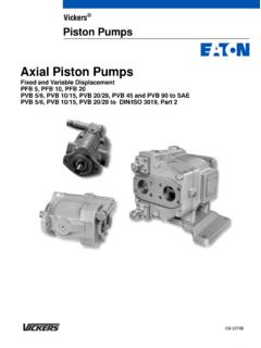
Transcription of Overhaul Manual Pumps Inline Piston Pumps
1 M-2200-SRevised 12/1/85 Inline Piston PumpsM-PFB & M-PVB SeriesVickers PumpsOverhaul Manual2 Table of Purpose of Manual3.. B. General Information3.. General4.. B. Assembly and Construction4.. C. Application4.. of OperationA. General5.. B. Fixed Displacement Pump5.. C. Variable Displacement Pump5.. and Operating InstructionsA. Installation6.. B. Drive Connections6.. C. Mounting6.. D. Shaft Rotation6.. E. Hydraulic Tubing6.. F. Inlet Line7.. G. Filtration7.. H. Hydraulic Fluid Recommendations7.. I. Overload Protection8.. J. Starting and Priming8.
2 Service Tools9.. B. Inspection and Service9.. C. Adding Fluid to the System9.. D. Lubrication9.. E. Replacement Parts9.. F. Adjustments9.. G. Product Life9.. H. Troubleshooting9.. General11.. B. Disassembly12.. C. Inspection and Repair14.. D. Assembly15.. E Eaton Hydraulics, Incorporated 2000 All Rights Reserved3 Section I IntroductionA. Purpose of ManualThe purpose of this Manual is to describe the basicoperational characteristic and to provide service andoverhaul information for Vickers Fixed and Variable DeliveryInline Piston Pumps . Models included in this series are listedin Table 1.
3 Information contained in this Manual pertains tothe latest designs. Earlier designs are covered only to theextent of their similarity to present General InformationRelated Publications Service parts information andinstallation dimensions are not contained in this Manual . Theinstallation drawings and parts catalogs listed in Table 1 areavailable from Codes There are many variations within each basicmodel series, which are covered by variables in the model 2 is a complete breakdown of the code covering theseunits. Service inquiries should always include the complete unitmodel number, which is stamped on the DrawingParts CatalogM-PFB5M-PFB10M-PFB20M-PVB5M-PVB10 M-PVB20M 289424M 289419M 289426M 289424M 289419M 289426M-2201-SM-2202-SM-2203-SM-2211-SM- 2212-SM-2213-STable 1.
4 Installation Drawings and Parts CatalogsModel Code224567 891013111 Mobile release13123 PumpDelivery typeF Fixed displacementV Variable displacement4 Inline pistonPump type5 DeliveryGPM rating at 1800 RPM6 Rotation (viewing from shaft end)R Right handL Left handU Either direction10 Control type (variable Pumps only)C Pressure compensator (250-3000 psi range)The compensator is adjusted tothe minimum setting at the LeverD Stem servo7 Yoke travel (variable Pumps only)D Both sides of centerS One side of center8 Shaft typeG SAE splined shaft* Omit for straight keyed shaft9 Pump design numbersDesign numbers subject to dimensions remain as shownfor design numbers 10 thru control location (levermodels only)L Left hand side-viewing shaft end;omit for right hand side as shownon installation design numbers(Variable Pumps only; omit for fixedpumps)Design numbers subject to dimensions remain asshown for design numbers 10 thru features suffixTable 2.
5 Model CodeP4 Section II DescriptionA. GeneralInline Pumps are of the axial Piston , positive displacementtype and include both fixed and variable (adjustable)displacement Pumps capable of high pressure speeds vary with the model, type of fluid used andcircuit Assembly and ConstructionThe assembly of typical fixed and variable displacementunits together with their ASA symbols are shown in Figure illustrated, the major components of the fixed in-line unitare the housing, drive shaft, rotating group, swash plate andvalve plate. The variable displacement units incorporate amechanism which governs the angle of the swash plate andconsequently controls the stroke length of each Piston as thecylinder block and drive shaft rotate.
6 The valve platesubassembly also serves as the back cover of the entire unitand includes the inlet and outlet ports. A bearing in the coverand one in the housing support the drive ApplicationThe installation drawings give the nominal pumpperformance characteristics and limits. For applicationsoutside of the given limits the mobile sales applicationengineer should be Fixed Displacement PumpTypical Variable Displacement PumpPort ConnectionsValve PlateRotating GroupSwash PlateShaft SealBearingDrive ShaftHousingPort ConnectionsCompensatorControl PistonYoke SpringDriveShaftHousingPintleRotating GroupValve PlateBearingShaft SealSwash PlateYokePFPVC ontrolDRDR5 Section III Principles of OperationA.
7 GeneralRotation of the drive shaft imparts a reciprocating motion tothe pistons with respect to their cylinder block bores, as aresult of the angularity between the axis of rotation of thedrive shaft and the plate of the Piston shoe bearing surfaceon the swash plate (see Figure 2). Each Piston reaches twodead-center positions in one revolution or the Piston revolves past the top dead-center position(when the Piston is nearest the valve plate), it begins towithdraw from the cylinder block bores and thus begin itsintake or suction stroke. During the intake stroke of thepiston, fluid is drawn into the corresponding cylinder blockbore through a porting arrangement located on the face ofthe valve plate and cylinder the Piston reaches bottom dead-center position (when thepiston is furthest from the valve plate) its withdrawing motionceases, ending the intake stroke.
8 This point is 180_ from topdead-center. Further rotation of the cylinder block, andpiston, creates a return motion of the Piston towards thevalve plate and thereby establishes the discharge stroke ofthe Piston . During the discharge stroke, fluid is expelled fromthe cylinder block bore through the outlet port of the valveplate in a reverse manner to the intake the Piston reaches top dead-center, axial pistonmotion ceases, and the discharge stroke is ended. Thepumping cycle described above is made by each Piston as itand the cylinder block are revolved through PlateSlotOutletPortInletPortCylinderBloc k BorePiston SubassemblySwash PlateDrive ShaftB.
9 Fixed Displacement PumpsSince the swash plate angle in fixed displacement Pumps isnot variable, the output is determined by pump size and thespeed of Variable Displacement PumpsVariable displacement is affected by altering the angularitybetween the swash plate and the drive shaft axis as shownby views A, B and C in Figure pressure compensator is a spring-biased, pressureactuated, three-way valve incorporated onto the valve operation of the compensator is such that when thesystem pressure (pump outlet) reaches a pre-set value,determined by the compensator spring setting, the valvemoves to regulate the control pressure acting on theactuating Piston .
10 As the force produced by the actuatingpiston overcomes the force of the opposing springs, theswash plate angle moves toward the minimum displacementposition, view C, Figure 3. The amount of angular movementof the swash plate ( , displacement change) is determinedby system flow demand and the resulting system is achieved when the new displacement ( ,pump delivery) matches the system swash plate angle(maximum displacement)Decreased swash plate angle(partial displacement)Zero swash plate angle(minimum displacement)ABC6 Section IV Installation and Operating InstructionsA.