Transcription of Overhaul Manual Vane Motors Vane Motors - Eaton
1 M-2740-SRevised 05-01-86 Vane Motors25M, 35M, 45M, 50 MSeries -20 DesignOverhaul ManualVickers Vane Motors2 Table of Purpose of Manual3.. B. General Information3.. General4.. B. Assembly and Construction4.. C. Mounting4.. D. Application4.. of OperationA. General5.. B. Cartridge Action5.. C. Hydraulic Balance5.. D. Vane Balance5.. E. Dual Alternate Pressure Plates6.. and Operating InstructionsA. Installation Drawings6.. B. Mounting and Drive Connections6.. Rotation and Drive Speeds6.. D. Piping and Tubing7.. E. Hydraulic Fluid Recommendations7.. F. Overload Protection7.. G. Drain Connection7.
2 H. Port Positions8.. , Inspection and MaintenanceA. Service Tools9.. B. Inspection9.. C. Adding Fluid to the System9.. D. Lubrication and Adjustments9.. E. Replacement Parts9.. F. Product Life9.. G. Troubleshooting9.. General11.. B. Disassembly11.. C. Inspection and Repair11.. D. Reassembly11.. 3 Section I IntroductionA. Purpose of ManualThis Manual has been prepared to assist the users ofVickers high performance vane Motors in properly installing,maintaining and repairing their units. The vane Motors aredescribed in detail and their theory of operation is discussed,in addition to instructions for installation, maintenance general series of models covered are 25M, 26M, 35M,36M, 45M, 46M, 50M and 51M.
3 The information givenapplies to the latest design series listed in Table 1. Earlierdesigns are covered only insofar as they are similar topresent General InformationRelated Publications Service parts information and instal-lation dimensions are not contained in this Manual . The partscatalogs and installation drawings listed in Table 1 are avail-able from vickers sales Series -13M-273813M-2701-SM2-300 Series -13M-142085M-2703-SM2-400 Series -13M-142041M-2705-SM2-500 Series -13M-142042M-2707-STable 1. Parts and Installation DrawingsModel Codes There are many variations within each basicmodel series, which are covered by variables in the modelcode.
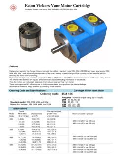
4 A complete breakdown of the codes covering these unitsare in Table 2. Service inquiries should always include thecomplete unit model number as stamped on the motor Designation133 Vane motor (Externally drained)Ring Size Nominal Torque Rating(lb. in. / 100 psi)8 Design Number5 Mounting Flange and PortConnectionsTable 2. Model Code Breakdown6 Shaft TypeFoot Bracket Mount and Position(Leave blank if foot bracket mountnot required; body viewed from shaftend with respect to foot bracket.)Cover Position (Viewed fromcover end)25 Standard Bearing26 Heavy Duty Bearing35 Standard Bearing36 Heavy Duty Bearing45 Standard Bearing46 Heavy Duty Bearing50 Standard Bearing51 Heavy Duty Bearing525M30 lb.
5 Lb. lb. lb. lb. lb. lb. lb. lb. lb. lb. lb. lb. SAE type 2-bolt mounting flange and SAE 4-bolt flanged portconnections2 Body Port at 12 o clock position3 Body Port at 3 o clock position6 Body Port at 6 o clock position9 Body Port at 9 o clock position1 Straight Keyed11 SplinedA Cover port opposite body portB Cover port 90_ counterclock-wise from body portC Port connections in lineD Cover port 90_ clockwise frombody portDesign numbers subject to dimensions remain thesame for design numbers 20 thru Features4 Section II DescriptionA. GeneralVickers high performance vane Motors , when properlyinstalled in a hydraulic circuit, convert hydraulic power intorotary mechanical power.
6 They are positive-displacement,balanced cartridge units, with drive speed dependent on themotor size and gpm delivery to the inlet port. The units arecapable of operating at high speeds and high pressures, orhigher speeds at lower pressures. These Motors may beoperated in either direction of rotation, reversed or stalledunder load conditions without Motors covered in this Manual are basically identical inconstruction. The Motors are designed so that the maximumtorque capability can be changed within a series by changingthe cartridge or the cam Assembly and ConstructionBasic motor construction is illustrated in Figure 1.
7 The unitconsists principally of a body, cover, drive cartridge andshaft. Rotary motion is developed in the cartridge, which prin-cipally consists of a ring, rotor, ten vanes and two pressureplates. The rotor is splined and mates with the output shaft,which is supported by a ball bearing in the body and a bush-ing bearing in the cover pressure vanes slide radially in the rotor slots and follow theelliptical cam contour of the ring as the rotor turns. Thesevanes are held against the ring by a combination of springand centrifugal connections are located in the body and cover. Directionof shaft rotation is governed by the direction of fluid flowthrough these ports.
8 Pressure is sealed from one port to theother by a Teflon sealing ring in the body on the periphery ofthe ring. Drainage is ported through an external connectionin the cartridge is bolted together and can be serviced as acomplete assembly. Locating pins position the ring with re-spect to the pressure plates, and in like manner, two torquepins position the cartridge in the cover. The cover can beassembled in four positions with respect to the body. Chang-ing of the port positions is accomplished by rotating the coverand MountingThe Motors are body face mounted, or are available with anoptional foot mounting (see Section IV).
9 The body mountingis a standard SAE 2-bolt ApplicationsVickers high performance vane Motors are rated in pound-inches of torque per 100 psi. Horsepower output is propor-tional to drive speed so long as pressure is constant. Forapplication information, refer to the appropriate installationdrawing (Table 1) or consult vickers application 1. Cutaway View of Vane PortVaneSpringDrainBushingCoverPressureP lateRingRotorBody Pressure PlateBearingFelt WiperShaftShaft SealHub AdaptorBody PortTeflon RingO-ring5 Section III Principles of OperationA. GeneralRotation of the motor shaft is caused by differential pressureacross the motor exerting a force against the vanes.
10 Thisforce is in effect tangential to the rotor and causes the rotorto turn, carrying the motor shaft with fluid is directed into the motor through the body port (seeFigure 2), shaft rotation, as viewed from the shaft end, isclockwise. When the oil supply is directed to the cover port,rotation is counterclockwise, as viewed from the shaft the direction of fluid flow thus changes the direc-tion of motor rotation. This is usually accomplished by theuse of a suitable directional control valve. With either portopen to pressure, the other port becomes the return PressureReturn PressureOperating PressuresB.