Transcription of Overview of 3.3V CAN (Controller Area Network) …
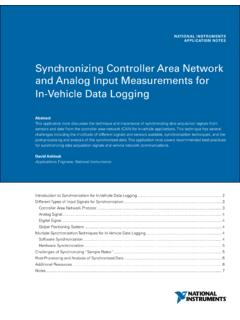
1 Application Report SLLA337 January 2013 1 Overview of CAN ( controller area network ) Transceivers Jason Blackman and Scott Monroe ABSTRACT CAN ( controller area network ) transceivers offer advantages and flexibility with respect to 5V CAN transceivers while being compatible and interoperable with each other. Power consumption is lower with transceiver compared with 5V transceivers. There is potential for power supply simplification and cost savings when the microprocessor communicating with the transceiver is also at Some implementers of CAN buses may be skeptical to use transceivers due to the legacy of 5V transceivers that are known to perform well. There may be uncertainty of performance in mixed supply CAN buses. This application note demonstrates the interoperability of and 5V CAN transceivers in addition to explaining the theory of operation.
2 Contents 1 THEORY OF OPERATION .. 2 2 MEASUREMENTS DEMONSTRATING OPERATION .. 4 3 CONFORMANCE TESTING .. 9 4 DEVICE ADVANTAGES .. 10 5 SUMMARY .. 11 SLLA337 2 Overview of CAN ( controller area network ) Transceivers 1 THEORY OF OPERATION The ISO 11898 specification details the physical layer requirements for CAN bus communications. CAN is a low-level communication protocol over a twisted pair cable, similar to RS-485. Figure 1. Typical CAN network An important feature of CAN is that the bus isn t actively driven during logic High transmission, referred to as recessive. During this time, both bus lines are typically at the same voltage, approximately VCC/2. The bus is only driven during dominant transmission, or during logic Low. In Dominant, the bus lines are driven such that (CANH CANL) This allows a node transmitting a High to detect if another node is trying to send a Low at the same time.
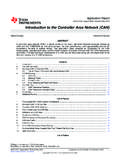
3 This is used for non-destructive arbitration, where nodes start each message with an address (priority code) to determine which node will get to use the bus. The node with the lowest binary address wins arbitration and continues with its message. There is no need to back-off and retransmit like other protocols. CAN receivers measure differential voltage on the bus to determine the bus level. Since transceivers generate the same differential voltage ( ) as 5V transceivers, all transceivers on the bus (regardless of supply voltage) can decipher the message. In fact, the other transceivers can t even tell there is anything different about the differential voltage levels. SLLA337 Overview of CAN ( controller area network ) Transceivers 3 RecessiveLogic HDominantLogic LRecessiveLogic HTime, tTypical Bus Voltage (V)CANLCANHV diff(D)Vdiff(R)12345V CANR ecessiveLogic HDominantLogic LRecessiveLogic HTime, tTypical Bus Voltage (V)CANLCANHV diff(D)Vdiff(R) CAN Figure 2.
4 Typical CAN Bus Levels for 5V and Transceivers Figure 2 (above) shows bus voltages for 5V transceivers as well as transceivers. For 5V CAN, CANH and CANL are weakly biased at about (VCC/2) during recessive. The recessive common-mode voltage for CAN is biased higher than VCC/2, typically about This is done to better match the common mode point of the 5V CAN transceivers and minimize the common mode changes on the bus between and 5V transceivers. Since CAN was defined as a differential bus with wide common mode allowing for ground shifts (DC offsets between nodes) this isn t needed for operation, but will minimize emissions in a mixed network . In addition, by using split termination to filter the common mode of the network a significant reduction in emissions is possible. The ISO 11898-2 standard states that transceivers must operate with a common-mode range of -2V to 7V, so the typical common-mode shift between and 5V transceivers doesn t pose a problem.
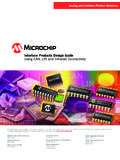
5 SLLA337 4 Overview of CAN ( controller area network ) Transceivers 2 MEASUREMENTS DEMONSTRATING OPERATION Figure 3. Waveforms of Two 5V SN65 HVD255 Transceivers Figure 3 (above) shows two 5V transceivers communicating on the same bus. In this case, transceiver (XCVR) 1 and 2 are both Texas Instruments SN65 HVD255 CAN transceiver . The signals TXD1 and TXD2 show what each transceiver is driving onto the bus, while RXD1 and RXD2 show what each transceiver is reading from the bus. The two upper signals are the bus lines, CANH (yellow) and CANL (light blue). The red waveform below them is the calculated dif ferential voltage between CANH and CANL. A simplified bit pattern was used to demonstrate CAN bus principles. Bit time 1: one transceiver transmits a dominant bit while the other remains recessive. Bit time 2: both transceivers are recessive. Bit time 3: both transmit dominant, showing what would happen during arbitration.
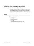
6 As shown the differential voltage is slightly greater when both transceivers are dominant due to the output transistors of each transceiver being in parallel, resulting in a smaller voltage drop and greater differential voltage output. SLLA337 Overview of CAN ( controller area network ) Transceivers 5 Figure 4 (below) shows the same setup but with two transceivers (TI SN65 HVD234). The differential voltage between the bus lines during dominant bits is lower than the 5V devices that were tested, but is still meets the requirements of the ISO 11898-2 standard. In addition, the guaranteed minimum differential bus voltage for the 5V devices is the same as with the devices ( ). This means that designers have no advantage if choosing 5V devices for their higher differential driving abilities, since there is no guarantee that the differential output will be higher.
7 Figure 4. Waveforms of Two SN65 HVD234 Transceivers SLLA337 6 Overview of CAN ( controller area network ) Transceivers Figure 5. Waveform of Two SN65 HVD255 Transceivers, One with a +1V Ground Shift Figure 5 (above) shows how robust CAN is with common mode differences. The red Math signal shows the common mode voltage instead of differential voltage in previous plots. The bus signals become very ugly when arbitration between ground shifted transceivers occurs. However, the RXD1 signal shows that the transceivers don t have a problem because the differential signal is good and the transceiver correctly detects the signal on the bus. SLLA337 Overview of CAN ( controller area network ) Transceivers 7 Figure 6. Waveform of Two 5V SN65 HVD255 Transceivers with Split Termination, One with a +1V Ground Shift Figure 6 (above) shows the same situation as the previous figure, now with split termination instead of traditional single termination.
8 Split termination, shown below, helps filter out high frequency noise which can occur when there are ground potential differences between nodes. The setup for Figure 6 used a CL of , which is typical. CANLCANHRLCANLCANHRL/2RL/2CL Figure 7. Single Termination (left) and Split Termination (right) SLLA337 8 Overview of CAN ( controller area network ) Transceivers Figure 8. Waveform of a 5V SN65 HVD255 and a SN65 HVD234 Figure 8 (above) shows communication with a mixed network of one transceiver and one 5V transceiver . As before, the digital signals TXD1, TXD2, RXD1 and RXD2 show that both transceivers are accurately talking to each other and there is little common mode shift during the communication in contrast to the 5V homogeneous network with a 1V ground shift. SLLA337 Overview of CAN ( controller area network ) Transceivers 9 Figure 9. Bus Communication of a 5V SN65 HVD1050 and a SN65 HVD230 Figure 9 (above) shows a CAN frame in a mixed network of two transceivers and one 5V transceiver to demonstrate these principles in a CAN frame from a functional mixed system.
9 3 CONFORMANCE TESTING The TI SN65 HVD23x CAN families have been successfully tested by the internationally recognized third party communications and systems (C&S) group GmbH to the GIFT/ICT CAN High-Speed transceiver Conformance Test. This testing covers a homogeneous network of all transceivers and a heterogeneous network where four out of sixteen CAN nodes are the transceiver and the remaining twelve CAN nodes are a mix of three other golden reference, non TI 5V CAN transceivers. Both TI CAN transceiver families successfully passed this testing with no findings and the certificates of authentication were issued. SLLA337 10 Overview of CAN ( controller area network ) Transceivers 4 DEVICE ADVANTAGES The transceivers tested clearly operate in mixed supply networks, so now let s look at their advantages. The first advantage is lower power.
10 Not only are transceivers lower voltage, they are also lower current. Table 1. Chart of Supply Current for Three Different Two-Node Buses Case 1: 2X SN65 HVD234 SN65 HVD234 #1 ICC (mA) SN65 HVD234 #1 ICC (mA) Both recessive #1 dominant Both dominant Case 2: 2X SN65 HVD255 SN65 HVD255#1 ICC (mA) SN65 HVD255 #1 ICC (mA) Both recessive #1 dominant Both dominant Case 3: Mixed SN65 HVD234 ICC (mA) SN65 HVD255 ICC (mA) Both recessive SN65 HVD234 dominant SN65 HVD255 dominant Both dominant Table 1 shows the supply current for devices is reduced by nearly half. Combined with the already lower supply voltage, this results in significant power reduction. SLLA337 Overview of CAN ( controller area network ) Transceivers 11 Several other advantages emerge when used with a microcontroller. The digital I/O of a 5V transceiver would be level shifted either externally or in the 5V CAN transceiver to avoid damaging the microcontroller (unless it is 5V tolerant) where as a transceiver could be directly connected to this microcontroller.