Transcription of OWNER’S GUIDE - International Greenhouse Company
1 WARNINGS: Always inspect your sprayer thoroughly before use. Be sure hose is securelyattached and in good condition. Test with water at the beginning of eachseason. Always follow directions on spray material containers. Read them thoroughlyand follow carefully. Always wear protective clothing (goggles, face masks, long sleeves, longpants, gloves, etc.) when spraying as is recommended by the manufacturerof the spray material. Do not allow spray to reach people or animals. Always release air pressure before removing pump or servicing sprayer inany way by unscrewing the pressure control valve. Always point the telescoping wand away from yourself or others while adjusting. Do not use flammable materials in this sprayer, as this could cause the sprayerto explode. Do not use caustic, acidic, or corrosive materials in this sprayer, as they couldweaken and corrode the parts, which could lead to injury. Do not use solutions hotter than 105 F.
2 Do not damage or alter the function of the pressure control valve or plug thepressure control valve, as this could cause the sprayer to explode. Do not over-tighten handle and base screws. This will prevent stripping andloosening of the parts. Do not pressurize sprayer until ready to use. Do not leave pressurized sprayerunattended. Carry back pack sprayer by carry handle or straps only. Clean tank, pump and valve thoroughly with soap and water after herbicidesand other poisons have been used. If nozzle clogs do not force open with air pressure. Remove nozzle and cleanwith fine wire or toothpick. Read and follow all instructions in sprayer manual before using. FAILURE TO HEED ALL SAFETY INSTRUCTIONS AND WARNINGS COULDRESULT IN SERIOUS BODILY TO PREPARE YOUR BACK PACK SPRAYER FOR adjust pump handle to pumping position, remove retaining clip on bottomof tank base (fig. 4, item 41) and pull pump handle out until and insert install pump handle on opposite side of sprayer, remove retaining clipon bottom of tank base and slide the pump handle out of center center crank (fig.)
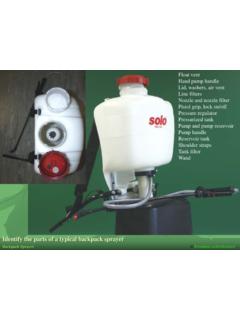
3 4, item 40) from bushing (fig. 4, item 42); movebushing to other side; turn center crank and snap back into bushing; reinsertpump handle from side and snap on telescoping extension wand to discharge valve by hand only. It isnot necessary to spray solution in separate receptacle, following directions on spraysolution cap at top of tank and pour solution into tank through the cap and tighten tank by pumping pump pressure by turning the pressure control valve on the pump. Turnpressure control valve to right to increase pressure; to left to packing seal nut (fig. 3, item 26) and tighten if loose to avoid leakageat pump strap attachment clip (fig. 2, item 13) can be snapped out of baseallowing either strap to be adjusted for easier mounting on the back. Afteradjustment, resnap clip back into the TO USE YOUR BACK PACK nozzle tip (fig. 6, item 67). Tighten tip for fine spray or loosen forcoarser spray or solid stream.
4 WARNING: Loosening tip too far will resultin tip coming off, allowing spray substance to spray back at you or inuncontrolled fan tip with fixed pattern replaces adjustable tip and body (fig. 6,item 68, 69, 70). Store optional fan tip assembly or adjustable nozzle tipassembly when not in use by snapping into storage slot in service panel(fig. 1, item 6). to maintain desired pressure level and spray should only be carried by carry handle or straps on back of caution when shortening telescoping wand as a small amount ofchemical will be discharged out of spray AND MAINTENANCE air pressure by turning pressure control valve (fig. 3, item 29) incounterclockwise cap (fig. 1, item 8) and pour out any remaining spray all parts thoroughly with clean a small amount of clean water in tank, pressurize and flush hoseand discharge DISASSEMBLE PUMP FOR the service panel (fig. 1, item 6) by pressing on the three tabslocated on the center and sides of the panel.
5 Pull the panel out throughthe bottom of the hose through bottom of tank retaining clip ( , item 41) from bottom of tank base. Removepump pump cap (fig. 1, item 5) by turning counterclockwise until it is freeof the threads and remove through bottom of tank pump housing (fig. 3) out of tank O-ring (fig. 3, item 17) for damage or wear. Replace if filter screen (fig. 3, item 18) for dirt or debris. Rinse with clear wateror replace if pressure control valve (fig. 3, item 29) adjusting knob by turningcounterclockwise. Inspect for damage or wear. Replace if pressure chamber (fig. 3, item 21) from pump cylinder (fig. 3, item16). Inspect O-ring (fig. 3, item 20) for wear. Replace if necessary. Removecheck valve (fig. 3, item 19) on top of pump cylinder. Inspect all sealingsurfaces on both the valve and the cylinder areas for debris and is important for these areas to remain clean or the unit will notpressurize.
6 Replace check valve if the pump nut (fig. 3, item 25) to reveal the pump cup retainerassembly (fig. 3, item 22 & 23). Carefully inspect the external surfaces ofthe cup for scratches or cracking. Also inspect the mating pump cylinderwalls for scratches. Excessive wear will cause the pump to lose as the packing seal nut (fig. 3, item 26) from the pump nut (fig. 3,item 25). Inspect all sealing surfaces on the rod and nut for as pump nut O-ring (fig. 3, item 24) for damage or wear. Replace pump assembly to tank, making sure that the discharge hoseis aligned to the groove in the base prior to tightening the pump cap. Itis important for the hose to be aligned to the base so that the hose doesnot interfere with the pumping operation during SHOOTING GUIDEPROBLEMPOSSIBLE CAUSESOLUTIONS prayer will not Check valve (item 19) is Replace check Pressure chamber O-ring (item 20) is damaged or Replace leaks at Packing seal nut (item 26) is Tighten the packing seal nut (26) securely by Pump nut O-ring (item 24) is Replace Pump cup (item 22) is worn or Replace pump Pressure control valve (item 29) turned too far Turn valve to the right to increase Filter screen (item 18) is Clean or replace filter leaks at extension Extension cap is Tighten extension cap securely by nozzle fails to Dirt or debris is lodged in nozzle Unscrew nozzle tip from wand and clean nozzle bodyand cap using a toothpick or broom POLICY.
7 ONE YEAR LIMITED WARRANTYIf this Spray Doc back pack sprayer does not give the user complete satisfaction due to defect in material or workmanship within one year of the date of purchase, themanufacturer will at its option repair or replace the product or component part free of charge. If this Spray Doc back pack sprayer is used for commercial or rentalpurposes, this warranty coverage applies for only 90 days from the date of no event shall the manufacturer be liable for any indirect, incidental or consequential damages from the sale or use of the product. Some states do not allow the exclusionor limitation of incidental or consequential damages, so the above limitation or exclusion may not apply to warranty service, please return the complete unit, transportation prepaid, to Gilmour Manufacturing Company , Customer Service Department, Somerset Industrial Park,Somerset, PA 15501. Should you have any questions, contact Customer Service at S GUIDENON-CORROSIVE, POLYETHYLENE BACK PACK SPRAYERMODEL NO.
8 BP4 PLEASE READ AND FOLLOW ALL INSTRUCTIONS BEFORE USING SPRAYERITEM NO.(S)DESCRIPTIONPART ASSEMBLY (FIG. 1)1-----------------TANK---------------- ---------------------------------------- -------------BP4202-----------------BASE ---------------------------------------- -----------------------------BP423 & 4-----------CLAMP KIT (3 SCREWS)--------------------------------- ----------BP4 CLAMP5-----------------PUMP CAP------------------------------------- -------------------------BP4216--------- --------SERVICE PANEL----------------------------------- -------------------BP4107--------------- --CAP STRAINER-------------------------------- -----------------------BP4238-10-------- ----TANK CAP ASSEMBLY-------------------------------- --------------BP4 CAPHANDLE/STRAP ASSEMBLY (FIG. 2)11&12----------STRAP KIT (STRAP & PIN)------------------------------------ ----BP4 STRAP13---------------STRAP CLIP------------------------------------ ------------------------BP4414&15------- ---HANDLE KIT (3 SCREWS)--------------------------------- --------BP4 HDLPUMP ASSEMBLY (FIG.)
9 3)16---------------PUMP CYLINDER-------------------------------- ---------------------BP43517------------ ---O-RING (TANK/PUMP CYLINDER)------------------------------O R156V7D18---------------FILTER SCREEN---------------------------------- --------------------BP4F2319------------ ---VITON CHECK VALVE----------------------------------- ---------100026V20---------------O-RING (PRESSURE CHAMBER)-------------------------------O R153V7D21---------------PRESSURE CHAMBER--------------------------------- ------------BP43422 & 23--------PUMP CUP RETAINER ASSEMBLY-----------------------------BP4 7724---------------O-RING (PUMP NUT)------------------------------------ ------------OR030V7 DITEM NO.(S)DESCRIPTIONPART ASSEMBLY CONTINUED (FIG. 3)25---------------PUMP NUT------------------------------------- -------------------------BP41326-------- -------PACKING SEAL NUT (ROD SEAL)------------------------------BP416 27 & 28--------ROD & PIVOT ASSEMBLY-------------------------------- ---------BP4 PRD29-34-----------PRESSURE CONTROL VALVE ASSEMBLY-------------------BP4 PCVPUMP CRANK ARM ASSEMBLY (FIG.
10 4)35-38-----------PUMP ARM ASSEMBLY-------------------------------- -------------BP4 PARM39---------------WAND CLIP------------------------------------ -------------------------BP41540-------- -------CENTER CRANK----------------------------------- ------------------BP4941---------------R ETAINING CLIP------------------------------------ ------------------BP43342--------------- BASE BUSHING--------------------------------- ----------------------BP414 DISCHARGE HOSE & VALVE ASSEMBLY (FIG. 5)43---------------GRIP----------------- ---------------------------------------- -------------10001544---------------SLEE VE-------------------------------------- ---------------------------10003345 & 46--------HOSE KIT (2 SCREW CLAMPS)--------------------------------- BP4 HOSE46-55-----------DISCHARGE VALVE ASSEMBLY (1 SCREW CLAMP)-----BP4 DISCDISCHARGE WAND & TIP ASSEMBLY (FIG. 6)56-64-----------TELESCOPING WAND ASSEMBLY-----------------------------BP4 WAND65-67-----------ADJUSTABLE TIP ASSEMBLY (CONE TO STREAM)------BP4 ADJ68-70-----------FAN SPRAY TIP ASSEMBLY-------------------------------- -------BP4 FANBP4 BACK PACK SPRAYER REPAIR PARTS LISTFIG.