Transcription of Owner’s Manual 917 & 918 Remote Control Switches
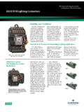
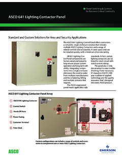
1 1 Owner s Manual917 & 918 Remote Control SwitchesTABLE OF CONTENTS pageRatings & Installation1 Accessories3 & Parts & Outline Diagrams back of is used in this Manual to warn of highvoltages capable of causing shock, burns, or possible personal possible equipment 917 Remote Control (RC) Switches are rated20 amperes non HID lighting loads and 30 amperesgeneral purpose. asco 918 RC Switches are preferredfor HID (high intensity discharge) loads such as sodiumvapor, mercury vapor, and metal halide lighting (controlvoltage is limited to 277 V).
2 asco 918 RC Switches arerated 30 amperes for standard ballast Number Identification with Elements ExplainedTypical asco 917 catalog no. for 12 pole 208 volt 60 Hz Control in an enclosure:917122061 Pole CombinationsProductControl VoltageAccessoriesX 2346810129440 480 V7265 277 VX347 V917918 EnclosureC blank open typeC6208 240 V3110 120 V50 60 Hzifaccessoriesorderedblank noneStandardN/O & N/C22 =2+233 =3+344 =4+466 =6+6277 V maximum Control voltage for asco 918381333 006 D50 Hanover Road, Florham Park, New Jersey 07932 1591 USAFor sales or service call 1 800 800 2726 ( asco )
3 POWER TECHNOLOGIES CANADA PO Box 1238, 17 Airport Road, Brantford, Ontario, Canada N3T 5T3telephone 519 758 8450, fax 519 758 0876, for service call 1 888 234 2726 ( asco ) 917 & 918 Owner s Manual2 These RC Switches are UL 508 listed and are availablein2to12polesinglethrowdoublebre akand2to6polenormally open and normally closed voltages are from 120 to 480 V ac. See tables A,B, and C for contact not exceed these values. Exceeding therating can cause personal injury or seriousequipment A Maximum AC Voltage and Current Ratingsfor asco 917 & 918 Main Contacts (open or closed)LoadAmperesCtiPoles to LoadLoadTypeContinuous1for2for1phaseType 9179181for1phase2for1phase3for 3 phaseGeneral3030347 V ac600 V acStandardBallast*2030347 V ac600 V acTungsten2020250 V ac250 V ac* asco 918 is preferred for HID and metal halide loadsTable B Maximum DC Voltage and Current Ratingsfor asco 917 & 918 Main Contacts (open or closed)
4 LoadTypeAmperesPoles to LoadLoadTypeAmperesContinuous2inSeries3i nSeriesGeneral20125 V dc250 V dcTable C Withstand Current Ratingsfor asco 917 & 918 Remote Control SwitchesAvailable Symmetrical Amperes RMSAtACWhen Used withMolded Case Circuit BreakersAtACService VoltageWithstandCurrent Rating(amperes)MaximumBreaker Size(amperes)250 V22,00030480 V14,00030600 V10,00030 Drawing IndexDrawing DescriptionStandard RC SwitchN/O & N/C RC SwitchPageRC Switch Outline & Mounting3610693838266 Outline & Mounting with Accessories3631643838977&8 Wiring Diagram3610683838259 Wiring Diagram with Accessories36316538388010 & 11 Enclosure Outline & Mounting36310436310412 InstallationASCO 917 & 918 Remote Control (RC) Switches arepre tested and ready to use.
5 Installation requiresmounting and connection of service cables and controlcircuit wires. An experienced licensed electrician shouldinstall the RC RC Switch has a ratings / identification labeldefining load types and maximum voltage ratings. not exceed the values on the rating the rating can cause personal injuryor serious equipment prevent malfunction or shortened life, protectthe switch from construction grit and metal :FiveOutline and Mounting Diagramsarefurnished. Select the appropriate diagram and mount theRC Switch. All mounting details and instructions RC switch can be mounted in any position but isusually mounted vertically.
6 Mounting holes in open typeRC Switches accept #10 screws (3/8 inch minimumlength). Enclosure mounting holes accept 1/4 inchdiameter and Load ConnectionsDeenergize the branch circuit to be connectedto the RC Switch and the Control line are reversible. The RC switch is UL listed foruse with 60 or 75 degrees C cable. All power wiresshould enter enclosure adjacent to the RC switchterminals. Combination knockouts are provided onNEMA Type 1 enclosures. Line and load connections aresupplied with clamp type terminals. These terminalsaccept the wire sizes #18 10 AWG Cu.
7 Insert appropri-ate line and load wires and tighten clamp screws to 18inch 917 & 918 Owner s Manual3 Control Line ConnectionsControl circuit connections designatedL,O,Con theright side are supplied with clamp type terminals. Theseterminals accept wire sizes #18 10 AWG Cu. Insertappropriate Control wires and tighten terminal clampscrews to 18 inch pounds. See theWiring all electrical connectionsto 18 inch overcurrent protective devices for thecontrol circuit in accordance with applicableelectrical D lists the maximum distances and minimum wiresizes that can be run between a Control station and oneASCO 917 or 918 Remote Control LineRunWireSizeMaximum Distance (feet)at ac Control voltageSize(AWG)
8 120 V240 V277 V347 V480 V147002,0002,6003,4005,500121,0503,1004, 1005,6008,800101,6705,0006,6009,00014,00 0Do not exceed these run can be extended by use of Control E lists the asco 917 & 918 coil inrush current andminimum Control circuit fuse E Inrush Current / Minimum FuseAmpsInrush Current / Fuse Size (amps RMS)at ac Control voltageAmps120 V240 V277 V347 V480 Contacts Optional Accessories 14H, 14 HAThese auxiliary contacts, if furnished, are installed ontheleftsideoftheRCswitch. Theauxiliarycontactsoperate along with the main contact to provide remoteindication of RC switch position (closed or open).
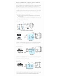
9 Each auxiliary contact provides a form C, spdt (singlepole double throw) contact rated 10 amps at 277 V 14H is one auxiliary contact, and Accessory14HA is two auxiliary contacts. A connector with leads isprovided for each auxiliary contact. SeeWiring Diagram363165 (page 10) or 383880 (page 11) for contactconfiguration, additional ratings, and Modules Optional Accessories 47, 48, 49 These Control modules, if furnished, are connected andmounted on the bottom or right side of the RC switchdepending on the number of RC switch poles or n/o andn/c contact configuration.
10 A Control module can be fieldinstalled by ordering the appropriate module asco . Refer to Wiring Diagram 363165 (page10) or 383880 (page 11).OperationAccessory 47control modules are for two wire Control the RC switch, and de energized to open the ,useasingle pole,maintained typecontrol station to operate the 48control modules are for three wire the RC switch; another terminal must be energizedto open the RC switch. If neither or both terminals areenergized, no output will occur. Therefore, use asingle pole, double throw, momentary type controlstation to operate the 49control modules are for Form 3 (start stop) Control of the RC switch.