Transcription of OWNER’S MANUAL Centrifugal Pumps - STA-RITE
1 owner 'S MANUAL . Centrifugal Pumps STA-RITE . 2791 0397. C and CC Series Installation/Operation/Parts For further operating, installation, or maintenance assistance: Call 1-888-782-7483. 293 WRIGHT STREET, DELAVAN, WI 53115 PH: 888-782-7483. 2013 Pentair, Ltd. All Rights Reserved. S150 (Rev. 02/04/13. Safety 2. READ AND FOLLOW. SAFETY INSTRUCTIONS! This is the safety alert symbol. When you see this symbol on your pump or in this MANUAL , look for one of the following signal words and be alert to the potential for personal injury: warns about hazards that will cause serious personal injury, death or major property damage if ignored. warns about hazards that can cause serious personal injury, death or major property damage if ignored. warns about hazards that will or can cause minor personal injury or property damage if ignored. The label NOTICE indicates special instructions which are important but not related to hazards. Carefully read and follow all safety instructions in this MANUAL and on pump.)
2 Keep safety labels in good condition. Replace missing or damaged safety labels. Motor normally operates at high temperature and will be too hot to touch. It is protected from heat damage during operation by an automatic internal cutoff switch. Before handling pump or motor, stop motor, and allow it to cool for 20 minutes. California Proposition 65 Warning This product and related accessories contain chemicals known to the State of California to cause cancer, birth defects or other reproductive harm. Table of Contents 3. Page General Troubleshooting ..8. Repair Parts ..9-11. Limited Warranty STA-RITE warrants to the original consumer purchaser ( Purchaser or You ) of the products listed below, that they will be free from defects in material and workmanship for the Warranty Period shown below. Product Warranty Period whichever occurs first: Water Systems Products jet Pumps , small Centrifugal Pumps , 12 months from date of original installation, submersible Pumps and related accessories or 18 months from date of manufacture Pro-Source Composite Tanks.
3 5 years from date of original installation Pro-Source Steel Pressure Tanks . 5 years from date of original installation Pro-Source Epoxy-Lined Tanks . 3 years from date of original installation 12 months from date of original installation, or Sump/Sewage/Effluent Products 18 months from date of manufacture Our warranty will not apply to any product that, in our sole judgement, has been subject to negligence, misapplication, improper installation, or improper maintenance. Without limiting the foregoing, operating a three phase motor with single phase power through a phase converter will void the warranty. Note also that three phase motors must be protected by three- leg, ambient compensated, extra-quick trip overload relays of the recommended size or the warranty is void. Your only remedy, and STA-RITE 's only duty, is that STA-RITE repair or replace defective products (at STA-RITE 's choice). You must pay all labor and shipping charges associated with this warranty and must request warranty service through the installing dealer as soon as a problem is discovered.
4 No request for service will be accepted if received after the Warranty Period has expired. This warranty is not transferable. STA-RITE SHALL NOT BE LIABLE FOR ANY CONSEQUENTIAL, INCIDENTAL, OR CONTINGENT DAMAGES. WHATSOEVER. THE FOREGOING WARRANTIES ARE EXCLUSIVE AND IN LIEU OF ALL OTHER EXPRESS AND IMPLIED. WARRANTIES, INCLUDING BUT NOT LIMITED TO THE IMPLIED WARRANTIES OF MERCHANTABILITY AND FITNESS. FOR A PARTICULAR PURPOSE. THE FOREGOING WARRANTIES SHALL NOT EXTEND BEYOND THE DURATION. EXPRESSLY PROVIDED HEREIN. Some states do not allow the exclusion or limitation of incidental or consequential damages or limitations on the duration of an implied warranty, so the above limitations or exclusions may not apply to You. This warranty gives You specific legal rights and You may also have other rights which vary from state to state. This Limited Warranty is effective June 1, 2011 and replaces all undated warranties and warranties dated before June 1, 2011. STA-RITE INDUSTRIES.
5 293 Wright Street Delavan, WI 53115. Phone: 1-888-782-7483 Fax: 1-800-426-9446 Web Site: Installation 4. Series C/CC Centrifugal Pumps The C and CC Series Pumps are close coupled Pumps with optional traps. CC Series have cast iron volutes and adapters. C Series have bronze volutes and adapters. Impellers on both series are bronze. Installation Location of Unit Install pump as close to liquid source as possible, using short, simple suction piping. Piping should be as direct as possible; elbows and other fittings greatly increase friction losses. Allow service and maintenance access. Mount on solid, rigid, vibration-free foundation. Protect pump against flooding and excess moisture. Piping Pump is not self-priming. Unless liquid source level is above pump suction at all times, install a foot valve on suction pipe. Support both suction and discharge piping independently near the pump to avoid placing strains on pump. Start all piping at pump to avoid strains left by a gap at last connection.
6 If possible, increase size of both suction and discharge piping if more than short runs are required. NOTICE: Never use a suction pipe smaller than the suction connection of the pump. NOTICE: If a reducer is necessary in the suction piping, always use an eccentric reducer with the straight side on top. NOTICE: BE SURE suction does not leak. Suction pipe must slope gradually upward to the pump. Avoid any fittings which might cause an air trap. Install gate valve and union in suction and discharge lines. If complete pump removal is required for service, close gate valves and disconnect at unions. Grounding the Motor Can shock, burn or cause death. Hazardous Ground motor before working voltage on pump or motor. Install, ground, wire and maintain this pump in accordance with the National Electrical Code, Article 250, or applicable local Codes and Ordinances. Ground the pump permanently using a wire of size and type specified by National or Local Electrical Code. Connect ground wire first.
7 Connect to ground first, then to motor terminal provide. Do not connect motor to electrical power supply until unit is permanently grounded. Any other sequence may cause serious shock hazard. Do not ground to a gas supply line. The motor grounding wire need not be larger than the wires supplying the motor, provided the supply wires conform to the wiring date included in this MANUAL (see Table I, Page 5). Installation / Maintenance 5. Wiring NOTICE: For 575 volt installations, see motor nameplate. Consult a licensed electrician for wiring information. Installation must meet code. For 200, 230, and 460 volt installations, check fusing/wiring data chart (Table I, below) before connecting pump to power source. Check that voltage/frequency on motor nameplate are identical with voltage/frequency of incoming power supply. NOTICE: Wire dual voltage motors correctly according to wiring diagram on motor. Check rotation of motor. Look through opening in adapter. Rotation should be clockwise when viewed from the motor end.
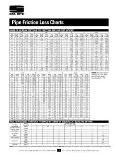
8 If not: Turn pump OFF and disconnect from power source. For three-phase motors, reverse any two leads to motor starter. For single phase motors, re-connect according to wiring diagram on motor. Priming the Pump NOTICE: NEVER run pump dry. To run pump dry may damage seals. To Prime: 1. If pump is installed below liquid source level, open gate valve in suction line and flood suction. 2. If pump is not installed below liquid source level, fill pump through a tee installed in pump discharge and fitted with a priming plug in the upright position. Tighten priming plug securely after priming! TABLE I - RECOMMENDED FUSING AND WIRING DATA - 60 CYCLE MOTORS. DIAMETER IN FEET FROM MOTOR TO METER (METERS). BRANCH 0'(0) 101'(31) 201'(62) 301'(92) 401'(123). MAX. FUSE* TO TO TO TO TO. MOTOR LOAD RATING 100'(30) 200'(61) 300'(91) 400'(122) 500'(152). HP PHASE VOLTS AMPS AMPS WIRE SIZE. 3 1 230 25 10 ( ) 10 ( ) 10 ( ) 8 ( ) 8 ( ). 3 3 200 15 14 (2) 14 (2) 12 (3) 10 ( ) 10 ( ). 3 3 230 15 14 (2) 14 (2) 12 (3) 12 (3) 10 ( ).
9 3 3 460 15 14 (2) 14 (2) 14 (2) 14 (2) 14 (2). 5 1 230 40 8 ( ) 8 ( ) 8 ( ) 6 (14) 6 (14). 5 3 200 25 10 ( ) 10 ( ) 10 ( ) 8 ( ) 8 ( ). 5 3 230 20 12 (3) 12 (3) 10 ( ) 10 ( ) 8 ( ). 5 3 460 15 14 (2) 14 (2) 14 (2) 14 (2) 14 (2). * Time delay fuse or circuit breakers are recommended in any motor circuit. IMPORTANT: BE SURE lead wire opening on end of bugs, etc. to enter back compartment of motor through motor is fully sealed when conduit or a pressure switch conduit opening and cause switch malfunction. is not used. Failure to seal it properly will allow dirt, rain, Maintenance 6. MAINTENANCE. Little or no maintenance to pump is required other than possible replacement of shaft seal after a reasonable period of operation (see below). Lubricate motor according to motor manufacturer's instructions. Periodic greasing is required for most motors. PUMP STORAGE. Drain pump to prevent freezing. Keep motor dry and loosely covered. Do not wrap with plastic sheeting;. trapped moisture could cause corrosion or insulation deterioration.
10 NOTICE: A good rust inhibitor in the liquid end of cast iron Pumps is recommended to prevent excessive corrosion. PUMP START-UP AFTER STORAGE. Replace all drain plugs and close all drain valves in system. Be sure all connections are tightly sealed. After inital check is made, fill pump according to Priming the Pump . above. Rotating Seal SHAFT SEAL REPLACEMENT. Spring NOTICE: The highly polished and lapped faces of the seal are easily damaged. Follow instructions and handle the seal with care. Stationary Be sure unit is grounded and power Seat Hazardous disconnected before attempting any voltage work on pump or motor. 1419 1294. Figure 1 REMOVAL OF OLD SEAL. Refer to Figure 1 for Mechanical Seal parts identification. 1. Remove motor hold down bolts and bolts holding adapter/seal plate to volute. Slide motor, adapter/seal plate and impeller backward to clear volute. Rotating Seat 2. Remove impeller screw and washer from end of shaft and slide will come off with If Gear Puller is used, impeller off of shaft.