Transcription of Owner’s Manual Refrigerated Compressed Air …
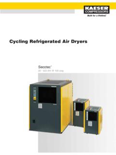
1 owner s Manual Refrigerated Compressed Air Dryers Model F-20 Read carefully before attempting to assemble, install, operate or maintain theproduct described. Protect yourself and others by observing all safety to comply with instructions could result in personal injury and/or propertydamage. Retain instructions for future : Air treated by this equipment is not suitable for breathing withoutfurther purifi cation. Refer to standards for the requirements for breathingquality 1 - F-20 ARROW DRYERS 745 CLARK AVE. BRISTOL, CT 06010 TOLL FREE: (877) 640-8300 Form F-0031 ARevised 10/041) Separator2) Compressor3) Expansion/Control Valve4) Refrigerant Filter5) Fan Motor6) Power On Light/Switch7) Dew Point Indicator8) Power Cord9) Drain Line1 Air FlowCompressorAftercoolerSeparator w/ Auto DrainAir ReceiverAir DryerCondensate Drain3 Valve dryer By-PassFigure 2 Receiving and inspectionArrow Dryers are carefully prepared for shipment at the factory to protect them from damage in transit.
2 Dryers are shipped factory. Immediately upon arrival, check the dryer for possible damage. If damage is found, report it to the carrier and file a damage the suction pressure gauge. If the suction pressure gauge reads zero, it indicates a possible refrigerant leak. Notify your dealer sure you have the right dryer . Check the nameplate for voltage and amperageHow the Air dryer WorksCompressed air enters the inlet and passes through the air-to-air heat exchanger where the air is partially cooled by the exiting cold air. Next, the air passes through a re-frigerant-to-air heat exchanger where it is cooled to near the freezing point of water. As the air is cooled, it loses the capacity to hold water vapor.
3 The water vapor condenses into water droplets and drains to the separator. Passing through the separator, air flow slows down and causes more water to condense and collect in the bottom of the separator bowl. The water is exhausted by the float drain (see figure 4).The Compressed air, now at a pressure dew point of 35 F, leaves the dryer through the air-to-air heat exchanger where it is heated by the incoming air. Location and InstallationLocate the dryer indoors in a protected area where ambi-ent temperature will range between 45 F and 100 F. Dryers are usually located near the compressor. Do not cycle the dryer with the compressor. If an aftercooler is used after the compressor, install the dryer downstream of the aftercooler and receiver (see figure 2).
4 Install the dryer so that there is sufficient room around it to permit circulation of air through the refrigeration condensing unit. Allow for easy access into the dryer through the cover the nameplate for voltage and amperage. The dryer is furnished with a 6 foot electrical cord for connection to a grounded dryer can be mounted on a wall with the key hole slots provided or on a floor sure that the compressor air passes through the dryer in the proper direction. Connect the Compressed air lines to the inlet and outlet connection as marked on the cabinet. Connect the air lines with standard pipe mechanical separator has an automatic float drain with a plastic drain line connection that exits through the dryer is recommended that a bypass line is piped around the dryer .
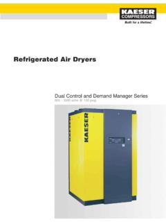
5 Shutoff valves should be installed at both inlet and outlet, with another valve in the bypass line. This complies with lockout regulations and permits the dryer to be removed from the system or serviced without turning off the air Compressed Air Systems23*Refrigerant R-134 ASpecifi cationsDimensionsF-20 Air DryerF-20 Wiring Diagram 115/220V CSIRM odelPowerCapacityDimensionsAir Line (Inches) Load AMP@ 100 PSIG Length * 3/8 1/610 3/8 1/610 3/8 1/610 Zone to Eliminate CarryoverFloat DrainBronze ElementWet Air EntersDry Air Exits Design ConditionsThe dryer must not be cycled with the air com-pressor. The dryer is non-cycling and is designed to run continuously (even under light loads).
6 If the Compressed air system remains pressurized and the air compressor cy-cles off and on to maintain line pressure, the dryer should remain in operation to keep the air lines Flow SCFM: The rated air flow (SCFM) of the dryer is designed for 100 PSIG. Above the rated air flow, the dew point will rise and moist air may reappear downstream. The dryer may cycle off and on under excessive load and cause compressor Air Temperature: The dryer will function normally up to 100 F. Above this temperature, the dryer capacity will fall off. Inlet air temperature should be controlled so that it does not exceed 100 Pressure: The maximum design pressure is 250 PSIG. The standard internal float drain in the separator will not rise and water will Air Temperature: Locate the dryer indoors in a protected area where the ambient temperature will range between 45 F and 100 F.
7 Note: Above an ambient temper-ature of 100 F the refrigerant will rise until the dryer shuts down. Several off and on cycles under these conditions will damage the Expansion Valve: The automatic expan-sion valve regulates the refrigerant suction pressure. The expansion valve is factory set between 33 and 36 PSIG. Start UPAlways turn the dryer on 5 to 10 minutes before the air compressor. This will allow the dryer to reach operating temperature and will prevent moist air down-stream of the dryer . After starting the dryer , the dew point indicator will slowly drop and hold be within the green area of the lighted on/off switch glows when the power is on.
8 Dur-ing normal operation, the light will be on and the gauge will read in the green area. If the gauge reads in lower red area, the cause is a low refrigerant charge or low ex-pansion valve setting. If the gauge reads in the higher red area, the compressor could be off. Other causes of a high gauge reading: a dirty air cooled condenser, high ambi-ent air temperature, high inlet air temperature or an air flow above the dryer s capacity. When the dryer is off, the gauge should read close to room temperature. How to Make Minor Refrigerant Suction Pressure Adjustments1) Keep the dryer running under no load and turn off or bypass the Compressed ) Remove the dryer cover and locate the control valve (See Figure 3).
9 3) Loosen the locknut and turn clockwise to increase or counterclockwise to decrease the suction pressure (1/4 turn will normally be enough). Tighten lockout securely and wait 3 to 4 minutes for the suction pressure to settle. Repeat if 3 Maintenance and CarePeriodically or as part of a preventative maintenance pro-gram, check the following:Be sure that there is a free flow of water from the separator drain. Check the drain mechanism and bronze element pe-riodically and clean monthly. The drain cock can be opened manually under pressure by turning the knurled clean the drain assembly, bypass the air supply. Re-move the bowl and then remove the float assembly and wash all part in warm soapy water.
10 Clean bronze element with kerosene. Reassemble in the reverse sure that there is a free flow of air over the condenser coils. Check the condenser fins periodically to prevent a build up of dust deposit. If fins are coated with dust, blow Compressed air through the fins to on refrigerant lines is an indication of too much re-frigeration capacity. This results in frozen air passages and prevents air flow through the dryer . It may be necessary to increase the refrigerant suction 4 Model F-205 TROUBLESHOOTING CHARTS ymptomPossible Causes(s)Corrective ActionUnit will not No Correct power supply, fuses, circuit Internal compressor Feel the temperature of the comp- ressor and allow to cool off if hot.