Transcription of owner’s Manual Self-Priming Centrifugal Pumps
1 owner 's Manual Self-Priming Centrifugal Pumps LT Series 1362 1111. Installation/Operation/Parts For further operating, installation, or maintenance assistance: Call 1-888-782-7483. 293 WRIGHT STREET, DELAVAN, WI 53115 PH: 888-782-7483. 2013 Pentair, Ltd. All Rights Reserved. BE976 (Rev. 02/22/13). Safety 2. Important Safety Instructions General Safety SAVE THESE INSTRUCTIONS - This Manual contains Risk of burns. Do not touch an operating important instructions that should be followed during motor. Motors can operate at high temperatures. To installation, operation, and maintenance of the product. avoid burns when servicing pump, allow it to cool for Save this Manual for future reference. 20 minutes after shut-down before handling. This is the safety alert symbol. When you see this Do not allow pump or any system component to freeze.
2 Symbol on your pump or in this Manual , look for one of To do so will void warranty. the following signal words and be alert to the potential Pump water only with this pump. for personal injury! Periodically inspect pump and system components. indicates a hazard which, if not avoided, will Wear safety glasses at all times when working on Pumps . result in death or serious injury. Keep work area clean, uncluttered and properly lighted;. indicates a hazard which, if not avoided, could store properly all unused tools and equipment. result in death or serious injury. Make workshops childproof; use padlocks and master indicates a hazard which, if not avoided, could switches; remove keys. result in minor or moderate injury. Keep visitors at a safe distance from the work areas. NOTICE addresses practices not related to personal injury.
3 Risk of explosion. Pump body may explode Keep safety labels in good condition. Replace missing or if used as a booster pump unless relief valve capable of damaged safety labels. passing full pump flow at 75 psi is installed. California Proposition 65 Warning This product and related accessories contain chemicals known to the State of California to cause cancer, birth defects or other reproductive harm. ire motor for correct W. WARNING voltage. See Electrical . WARNING. section of this Manual Hazardous pressure! and motor nameplate. Install pressure relief valve in discharge pipe. round motor before G. Release all pressure on connecting to power system before working on supply. any component. eet National Electrical M. Code, Canadian Hazardous voltage. Electrical Code, and Can shock, burn, or cause local codes for all death.
4 Wiring. Ground pump before connecting to power Follow wiring supply. Disconnect power instructions in this before working on pump, motor or tank. Manual when connecting motor to power lines. Warranty 3. Limited Warranty BERKELEY warrants to the original consumer purchaser ( Purchaser or You ) of the products listed below, that they will be free from defects in material and workmanship for the Warranty Period shown below. Product Warranty Period Water Systems: whichever occurs first: Water Systems Products jet Pumps , small Centrifugal Pumps , submersible Pumps and 12 months from date of original installation, or related accessories 18 months from date of manufacture Pro-Source Composite Tanks 5 years from date of original installation . Pro-Source Steel Pressure Tanks 5 years from date of original installation.
5 Pro-Source Epoxy-Lined Tanks 3 years from date of original installation . 12 months from date of original installation, or Sump/Sewage/Effluent Products 18 months from date of manufacture Agricultural/Commercial: Centrifugals close-coupled motor drive, frame mount, SAE mount, engine drive, VMS, 12 months from date of original installation, or SSCX, SSHM, solids handling, submersible solids handling 24 months from date of manufacture 12 months from date of original installation, or Submersible Turbines, 6 diameter and larger 24 months from date of manufacture Our limited warranty will not apply to any product that, in our sole judgement, has been subject to negligence, misapplication, improper installation, or improper maintenance. Without limiting the foregoing, operating a three phase motor with single phase power through a phase converter will void the warranty.
6 Note also that three phase motors must be protected by three-leg, ambient compensated, extra-quick trip overload relays of the recommended size or the warranty is void. Your only remedy, and BERKELEY's only duty, is that BERKELEY repair or replace defective products (at BERKELEY's choice). You must pay all labor and shipping charges associated with this warranty and must request warranty service through the installing dealer as soon as a problem is discovered. No request for service will be accepted if received after the Warranty Period has expired. This warranty is not transferable. BERKELEY SHALL NOT BE LIABLE FOR ANY CONSEQUENTIAL, INCIDENTAL, OR CONTINGENT DAMAGES WHATSOEVER. THE FOREGOING LIMITED WARRANTIES ARE EXCLUSIVE AND IN LIEU OF ALL OTHER EXPRESS AND IMPLIED. WARRANTIES, INCLUDING BUT NOT LIMITED TO IMPLIED WARRANTIES OF MERCHANTABILITY AND FITNESS FOR.
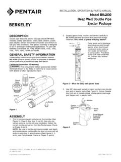
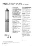
7 A PARTICULAR PURPOSE. THE FOREGOING LIMITED WARRANTIES SHALL NOT EXTEND BEYOND THE DURATION. PROVIDED HEREIN. Some states do not allow the exclusion or limitation of incidental or consequential damages or limitations on the duration of an implied warranty, so the above limitations or exclusions may not apply to You. This warranty gives You specific legal rights and You may also have other rights which vary from state to state. This Limited Warranty is effective June 1, 2011 and replaces all undated warranties and warranties dated before June 1, 2011. In the : BERKELEY, 293 Wright St., Delavan, WI 53115. In Canada: 269 Trillium Dr., Kitchener, Ontario N2G 4W5. Installation 4. priming Plug Offset suction flange adapter keeps suction water level above impeller eye to aid priming . Important: All connections must Discharge be air tight to service Union Support suction pipe Support discharge as required Gate Valve pipe as required Straight run, short as Solid, level possible but at least 6 base Some models have top times pipe diameter ("D"); discharge; these require slope is down going away a priming tee.
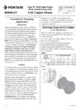
8 From pump. Pipe diameter "D". As close at least as large as as possible pump suction connection 4 x "D". minimum Recommended pump suction and discharge connections Figure 1. Misaligned pipe causes air leaks;. high spots along the suction line result in air pockets. On the discharge avoid: Quick closing valves. Small pipe. Numerous fittings. Misalignment. Long suction Sharp turns in piping run. run Use of excess fittings means potential air leaks Valve Unsupported Pipe High lift Pipe diameter "D". insufficient size Elbow immediately in front of pump suction. Not recommended pump suction Pipe submerged and discharge connections less than 4 x "D". will cause vortexing Figure 2 1239 0894. Installation / Electrical 5. Location Of Unit Wiring Locate the pump as near the liquid source as possible, 1.
9 Install, ground, wire and maintain this pump in using a short, direct suction pipe. Keep the static suction ac cordance with your local electrical code and all lift (vertical distance between the center line of the pump other codes and ordinances that apply. Consult your and the liquid level) to a minimum. Mount the pump local building inspector for local code information. on a solid, level foundation, which provides a rigid and 2. Ground the pump permanently using a wire of size vibration-free support. It should be located where the and type specified by local or National Electrical unit is readily accessible for service and maintenance. Code. Do not ground to a gas supply line. The pump should be protected against flooding and 3. Connect ground wire first. Connect to ground excessive moisture.
10 First, then to green grounding terminal provided Piping (identified as GRD or ). Make ground connection Both suction and discharge piping should be to this terminal. Do not connect motor to electrical independently supported at a point near the pump to power supply until unit is permanently grounded;. avoid strains being placed on the pump. Start all piping otherwise serious or fatal electrical shock hazard at pump to avoid strains left by a gap at last connection. may be caused. 4. For best ground connection, connect to a grounded Suction Piping lead in the service panel or to a metal underground The suction pipe must be kept free of leaks. The suction water pipe or well casing at least 10 ft. long. If pipe must have a gradual slope upward to the pump. plastic pipe or insulated fittings are used, run ground Avoid any fittings which may cause an air trap.