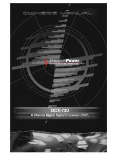
Transcription of OWNERS MANUAL - Precision Power
1 / / / / MANUAL <2>Table of ContentsCongratulations 3 Features 4 Specifications 5-6 Installation 7 Controls and Terminals 8-9 Control Definitions 10-12 System Diagrams 13-21 Troubleshooting 22<3>CONGRATULATIONST hank you for choosing Precision PowerTM audio equipment. Designed and engineered in the USA, this product combines innovative technology with the finest materials to consistently deliver Absolutely State of the Art perfor-mance, sound quality, reliability, and value. This Precision PowerTM product reflects our commitment to offer you unparalleled p erformance and quality for years of dependable service and listening not attempt to service Precision PowerTM products maintenance on your audio equipment will void the warranty.
2 Many parts of the Precision PowerTM product are custom built to our speci-fications. Our factory parts are not made available to anyone else nor are they for sale. Our goal is to make sure that your Precision PowerTM product will always sound as good as the day it was purchased. Contact your Authorized Precision PowerTM Dealer about obtaining any warranty service through Preci-sion PowerTM. CAUTIONE xtended use of a high powered audio system may result in hearing loss or damage. While Precision PowerTM systems are capable of Concert Level volumes with incredible accuracy, they are also designed for you to enjoy at more reasonable levels all of the sonic subtleties created by musicians.
3 Please observe all local sound ordinances.<4>FEATURES Sequenced Delays Eliminate Residual Power -Up/ Power -Down RCA Inputs Isolate 12V/Audio to Ground, Eliminating Ground Loops and Signal Path Low Noise/Distortion Circuitry Component Layout for Minimal Distortion Induction & Signal Darlington Audio Output StagesDifferential Drives Divide Pre-Amp & Power -Amp Stages, Eliminating Ground LoopingFull Differential Feedback Surrounding Power -Amp Stages directly from Speaker Ter-minals resulting in Uncolored Sound Reproduction and Elimination of Ground Loops Output Stage Bias Individually Sequenced, Optimizing Sound QualityStout 2 Oz.
4 Copper Traces Effortlessly Transfer High Volume Internal Current Close Tolerance Signal Path Components - 1% Resistors & 5% CapacitorsLarge TO218 MOSFET TransistorsHigh Volume, Low ESR Capacitance Banks Compensate Power Supply Ripple Cur-rentsExtra Low Current Drive Stage Increases Efficiency & Sound ClarityIndividually Regulated Preamp/Crossover Power Supplies Ensure Signal PuritySeparated Capacitor Charging/Discharging Current Paths Prevent Rail Switching Spikes & Ground Traces from Entering Signal Stages Resulting in Distortion<5> Power @ 4 , X 2195W X 270W X 4115W X 4 RMS Power @ 2.
5 X 2325W X 2100W X 4160W X 4 RMS Power @ 4 Bridged360W X 1650W X 1200W X 2320W X 2 Total Harmonic Distortion (4 Power ) Response15-50 KHz15-50 KHz15-50 KHz15-50 KHzInput Sensitivity200mV-9V200mV-9V200mV-9V200mV -9 VSignal-to-Noise Ratio (4 Power )102dB102dB102dB102dBDamping Factor (100Hz, 4 )>3000>1500>2000>3000 Dimensions: H X W X X 10 X X 10 X X 10 X X 10 X Channels 1&2 HPF (12dB Slope)15-4 KHz15-4 KHz15-4 KHz15-4 KHzChannels 1&2 LPF (12dB Slope)50-4 KHz50-4 KHz--Channels 3&4 HPF (12dB Slope)--15-4 KHz15-4 KHzChannels 3&4 LPF (12dB Slope)
6 --50-4 KHz50-4 KHzChannels 1&2 Bass Boost30-90Hz0-12dB30-90Hz0-12dB--Channel s 3&4 Bass Boost-30-90Hz0-12dB30-90Hz0-12dBRemote Gain ControlIncludedIncluded--External Fuse Required40806080<6> Power @ 4 , X 4, 275W X 1-RMS Power @ 2 , X 4, 450W X 11000W X 1 RMS Power @ 4 Bridged200W X 2-RMS Power @ 1 , x 1 Total Harmonic Distortion (4 Power ) Response15-50 KHz15-200 HzInput Sensitivity200mV-9V200mV-9 VSignal-to-Noise Ratio (4 Power )104dB102dBDamping Factor (100Hz, 4 )>1400>2400 Dimensions: H X W X L2 X 10 X X 10 X Channels 1&2 HPF (12dB Slope)15-4 KHz-Channels 1&2 LPF (12dB Slope)-50-200 HzChannels 3&4 HPF (12dB Slope)15-500Hz-Channels 3&4 LPF (12dB Slope)50-4 KHz-Channels 5 LPF (12dB Slope)50-200Hz-Bass Boost0-12dB(CH5 only)
7 0-12dB30-90 HzSubsonic Filter Slope 12dB15-50Hz15-50 HzPhase Control0 or 180/switch0 or 180/variableRemote Gain ControlIncludedIncludedExternal Fuse Required100150<7>InstallationBefore installing any audio equipment, it is good practice to disconnect the ground terminal on the battery to avoid damageto the vehicle or audio equipment. Failure to do this means you re a few brews short of a 6-pack and you probablyalready acquired the nickname of Sparky or Smokey . Not cool! Do NOT hook the ground cable back up to the batteryuntil the rest of the wiring is ground wire mayneed to be upgraded, especiallyif it is smaller than thepower wire, frayed, or must beinstalled within18 of a hole in the firewall &use a rubber grommet tokeep wire from the cables under thecarpet near the side of thevehicle.
8 Be careful not todrill or screw into thewires when replacing cable tobare metal chassis/frame with nut &bolt. No screws orseat/seatbelt bolts!Run signal cables (RCA)and remote turn-on leaddown the opposite side ofthe vehicle of the powerwire to avoid radiated sharp edgesthat could chafethrough the insulation.<8>TERMINALS* Power terminal block & Speaker terminal block for / * Power terminal block & Speaker terminal block for / * Power terminal block & Speaker terminal block for * Power terminal block & Speaker terminal block for <9>* Crossovers for / * Crossovers for * Crossovers for * Crossovers for / <10>Control DefinitionsAlrighty, here comes the fun stuff.
9 We re going to break this down to it simplest form so that there is no way you can possibly do any damage in the installation process to your audio system. We re going to explain in detail how every single knob and switch work rather than turn you loose on a sophisticated amplifier and have problems. READ EVERYTHING!Trust us, it ll be worth Before you do anything, undo the ground cable from the Terminal BlockGND This is the Ground connection. Bolt the Ground cable to a bare metal part of the chassis/frame. Do NOT us self-tapping screws or seat/seatbelt bolts!
10 +12V This is the Power Connection. This cable gets connected directly to the battery. You MUST use a fuse holder or circuit breaker within 18 of the battery. All cables ran through the firewall must be protected by a rubber or plastic grommet. If you have multiple amplifiers, the main fuse or circuit breaker at the battery should be the sum of all fuses or slightly This is the remote Turn-On connection. Connect to the amplifier output or Power antenna output of the source unit. If the unit does not have a switched +12V output, you can use another switchable + Terminal BlockThis is the Speaker(s) Connection.




![Abstract arXiv:1707.01836v1 [cs.CV] 6 Jul 2017](/cache/preview/4/1/7/c/3/c/f/5/thumb-417c3cf524207c81cbb20aac762ce5b4.jpg)