Transcription of Oxford Elevate (Rev A) - mpsource.com
1 Rev AOxford /Hoyer Professional SeriesSERVICE Rev ACONTENTSP ages 3 - 4 Inspection Criteria of the Oxford /Hoyer ElevatePage 5 Calibration of Weigh ScalePage 6 Load Testing of the Oxford /Hoyer ElevatePages 7 - 14 Service and Maintenance Schedule for the Oxford /Hoyer ElevatePage 15 - 16 Fault Finding on the Oxford /Hoyer ElevatePage 17 Exploded View of the Oxford /Hoyer ElevatePage 18 Parts List of the Oxford /Hoyer ElevatePage 19 LOLER (UK only): Thorough Examination ReportPage 20 - 23 AppendixPage 28 Blank Notes Rev AINSPECTION CRITERIAJ oerns Healthcare recommends a thorough inspection and test of the Oxford /Hoyer Elevate and its lifting accessories, slings carried out every six months including a weight test to the full examination and test should be conducted according to the recommendations and procedures below. Joerns Healthcarerecommends authorised service dealers should carry out maintenance, inspection and certified testing hoist is fitted with the optional weigh scales, the weigh scales require an annual calibration as described on page : These recommendations are in compliance with the requirements of 1998 No2307 Health and Safety: The Lifting Operationsand Lifting Equipment Regulations 1998.
2 (LOLER) This is a UK regulation. Outside the UK please check your local ARMC onfirm the presence and security of the sling retainers on the sling hooks or Securi3 clips (US model only).Check the sling hooks on the support arm for damage or for adequate padding on the support for secure attachment of the arm to the mast sure there is only minimal side movement of the arm and that it is free to rotate in the mast the arm is in alignment with the centreline of the the sling retaining bosses and clips on the actuator mounting bracket for damage or excessive the security and for wear on the actuator unit, mounting pin and mounting bracket on the arm.(Any excessive movement or play of the actuator, must be investigated).MASTC heck for secure attachment of the handle bar to the the mast is securely fitted in the base the operation of the mast-locking sure the mast fully engages onto the base for wear on the actuator unit mounting, mounting pin and mounting bracket on the mast.
3 (Any excessive movement or play of the actuator, must be investigated).POWER PACKC heck for secure attachment of the power pack mounting plate to the for secure attachment of the power pack to the mounting the function of the Emergency Stop the hand control for correct functioning in both directions, lift and the fit of the hand control plug and both actuator plugs for correct the operation of the emergency raise and lowering that the LCD battery level indicator shows the battery level when the emergency stop is released and shows stop whenthe emergency stop button is LEG ADJUSTMENTO perate the leg opening buttons on the hand control and check the legs open and close that the legs lock when the hand control button is the legs are parallel when they are in the closed Rev AINSPECTION CRITERIAKNEE PADC heck for secure attachment of the kneepad assy to the mounting bracket on the the kneepad is easily adjustable using the height-adjusting the kneepad assembly can t slide up or down when the height adjusting lever is the leg restraining straps for damage and wear fraying, loose stitching etc.
4 Ensure the buckles lock and release the condition of the kneepad for splits and or PLATEC heck for firm and secure fitment of the footplate to the footplate the foot tray for cracks or PIVOTSC heck the leg pivots are secure and the legs pivot freely. Any stiffness must be sure there is no excessive play in the leg all castors for firm attachment to the for free rotation of the castor and the any build up of threads, hair or if necessary with a light mineral based correct operation of the ACTUATORThe actuator should require no for correct for correct operation of mechanical emergency lowering device, this should be done by applying the full SWL to thesupport arms, raise the weight a short distance and carefully pull up the emergency lever, the weights should lower to the groundin a safe and controlled descent. This test should always be carried out with the full anti-crush precautions are for any unusual for wear on the mounting boss top and bottom.
5 (Any excessive movement or play of the actuator must be investigated).BATTERIESThe batteries in the power pack should not require maintenance, other than regular charging as detailed in the charging UNITC onfirm the charger unit is charging the battery mains plug is fitted with the properly rated the safety of the input and output lead CELL AND WEIGHT DISPLAY (Optional)Turn on the display and confirm the weight display indicates a reading of 0 (kg/lb) with no load on either the foot tray or support calibration is required see calibration procedure on Page with ordinary soap and water and/or any hard surface disinfectant. Harsh chemical cleaners or abrasives should beavoided as these may damage the surface finish of the lift. Avoid wetting any of the electrical Rev ACALIBRATIONWEIGH SCALE CALIBRATIONThe (optional) weigh scale can be calibrated as required, a certified calibration weight of either 10kg or 25lb is required. Pleasecontact Joerns healthcare if a calibration weight is on the weigh scales and by pressing and holding the LB/KG button select the correct units for the calibration weight,select KG if you are to use a 10kg weight else select LB if you are to use a 25lb start the calibration press and hold the ON/ZERO and LB/KG buttons simultaneously the display will change from ZERO to CAL , release both buttons and the display will show C 0 Ensure there is no weight applied to the foot tray or support arms, press the ON/ZERO button, the display will count down from16 to 0, during this time do not touch the display will now be showing C 10 if you are using a 10 kg test weight or C25 if you are using a 25lb test the calibration weight on the foot tray, press the ON/ZERO button, the display will count down from 16 to 0, during thistime do not touch the display will automatically return to the normal weighing mode.
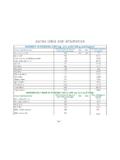
6 The calibration is now Rev ALOAD TESTINGLOAD TESTThe load test should be carried out in accordance with the manufacturers test procedures. It is strongly recommended that, anauthorised service dealer carry out the Electric hoists have been designed to the requirements of:1 BS EN ISO 10535 2006 Hoists for the transfer of disabled personsThe hoists are designed to lift the Safe Working Load only. The load lifting capability is set electronically and must not beincreased as this causes excessive loading when the actuator reaches the limits of travel. This will affect the actuator s useful BS EN ISO 10535 2006 Load Raising TestThis test is a straightforward lift of a load the equivalent to the Safe Working Load, from the lowest position to highest position ofthe hoist. Check that the hoist is not capable of lifting much more than the SWL (a small additional lifting capability is allowablebut no more than 5% of the SWL).TEST LOADS - Oxford /HOYER ARISE/ASCEND200kgs/440lbsCERTIFICATIONAn authorised service dealer will issue a test certificate after satisfactory completion of the thorough inspection and certificate will be valid for six Examination ReportLifting Operations and Lifting Equipment Regulations 1998 (LOLER UK ONLY)LOLER requires certain information to be included on the report given to a customer after a thorough examination.
7 Theinformation can be found in Schedule 1 (page 56) in the LOLER L113 Healthcare has prepared a Thorough Examination Report that includes all the required information. A copy can be foundon page 18. Please feel free to use this as the basis of your own Rev ASERVICE & MAINTENANCETOOLS REQUIRED 21mm A/F Spanner (for the rear castors) 17mm A/F Spanner (for the front castors) 19mm or inch A/F Spanner (for the mast and support arm fixing bolts) 9/16 inch A/F Spanner + Hex Key (for the mast/boom pivot bolt) 17mm A/F + 14mm Spanner (for the sling/actuator retaining boss bolt) inch A/F Spanner + 3/16 Hex Key (for the mast end lift and leg actuator bolts) 4mm Hex Key (for the screws on the handle bar base plate and all other fixings) 8mm Hex Key (for the screws securing the loadcell to mast) Calibrated Torque Wrench Medium Strength Thread lock (BLUE) TypeSUPPORT ARM1 The support arm is a two-piece assembly that is secured to the mast pivot by an arm pivot casting.
8 The arm pivot casting issecured to the end of the arm by two hexagon headed the grey plastic covers from the bottom of the support arm, the covers are a push on fit. Remove the covers bygently levering a thin blade or screwdriver between the boom and the that the two M12 hexagon headed bolts, are fully tightened to 15 the end caps from the black sling retaining bosses on the arm to reveal securing set that the set pin is fully tightened to 5 the actuator mounting point. Without taking the mounting point apart check for signs of wear on the fulcrum for excessive vertical and horizontal movement in the mounting. This will give a good indication of wear but if there is anydoubt the assembly should be stripped down as follows:7 Remove the set pin from the actuator the pin for signs of wear. The diameter of the fulcrum pin is Reduction in diameter due to wear must notexceed 1mm, before the outer sleeve bush from the support arm bracket and actuator top while holding the actuator, carefully lower theactuator to the ground.
9 (Take care not to loose the sling bosses and the sling retainers and nylon spacers on either side of theactuator on the inside wall of the boom).10 Examine the outer sleeve bush for wear this should not exceed the actuator mounting on the support arm for wear on the bore of the bracket this should not exceed the actuator top for wear this should not exceed the split bushes for wear this should not exceed the actuator to the boom bracket by replacing the sleeve, plastic washers, sling bosses and the sling retainersset pin and Tighten the nyloc nut to 5 the end caps for the sling Rev ASERVICE & MAINTENANCENOTE: Joerns Healthcare recommends Nyloc nuts should always be replaced if torque fasteners to the correct ARM PIVOT1 Check the pivot for lateral, vertical and horizontal play that would indicate excessive wear. Signs of excessive wear mustbe at the pivot point must not exceed 1 mm before the hoist is not fitted with optional weigh scale, remove the two plastic covers from the the hoist is fitted with optional weigh scale, the display can be removed by removing the battery and battery housing fromthe display housing and withdrawing the two screws which can be seen when looking through the battery hole - See appendix A.
10 Take care not to over-stress the cable connecting the display to the the Set pin is tightened to 8 the plastic covers, and display if applicable, to the Boom OF THE SUPPORT ARM PIVOT1To remove the support arm pivot, it is advisable to first remove the two M12 bolts from the end of the arm, this will enable thepivot to be removed and replaced more the hoist is not fitted with optional weigh scale, Remove the grey plastic covers from the top of the boom .The covers are apush on fit. Remove the covers by gently levering a thin blade or screwdriver between the boom and the covers2bIf the hoist is fitted with optional weigh scale, the display can be removed by removing the battery and battery housing fromthe display housing and withdrawing the two screws which can be seen when looking through the battery hole See appendix care not to over-stress the cable connecting the display to the loadcell3 Remove the bolts and pull the arm away from the arm pivot is held in place with a set the the pin for signs of wear.