Transcription of p Pages 629-650 CREO Lesson 14 Gary
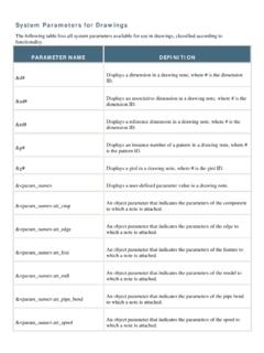
1 Creo parametric Lesson 14 2013 Cengage Learning. All Rights Reserved. May not be scanned, copied or duplicated, or posted to a publicly accessible website, in whole or in Lesson 14 Blends Figure Cap OBJECTIVES Create a Parallel Blend feature Use the Shell Tool Create a Swept Blend REFERENCES AND RESOURCES For Resources go to > click on the Creo parametric Book cover Lesson 14 Lecture Book Projects PDF Project Lectures Creo parametric Quick Reference Card Creo parametric Configuration Options BLENDS A blended feature consists of a series of at least two planar sections that are joined together at their edges with transitional surfaces to form a continuous feature.
2 The Cap in Figure uses a simple blend feature in its design. A Blend can be created as a Parallel Blend as used here, or you can construct a Swept Blend. Blend Sections Blended surfaces are created between the corresponding sections. Figure shows a parallel blend for which the section consists of several subsections. Each segment in the subsection is matched with a segment in the following subsection; to create the transitional surfaces; Creo parametric connects the starting points of the subsections and continues to connect the vertices of the subsections in a clockwise manner. By changing the starting point of a blend subsection, you can create blended surfaces that twist between the subsections.
3 The default starting point is the first point sketched in the subsection. Creo parametric Lesson 14 2013 Cengage Learning. All Rights Reserved. May not be scanned, copied or duplicated, or posted to a publicly accessible website, in whole or in Figure Blend Sections (CADTRAIN, COAch for Creo parametric ) Blend Options Blends (Fig. ) use one of the following transitional surface options: Straight Create a straight blend by connecting vertices of different subsections with straight lines. Edges of the sections are connected with ruled surfaces. Smooth Create a smooth blend by connecting vertices of different subsections with smooth curves.
4 Edges of the sections are connected with ruled (spline) surfaces. Parallel All blend sections lie on parallel planes in one section sketch. Rotational The blend sections are rotated about the Y axis, up to a maximum of 120 . Each section is sketched individually and aligned using the coordinate system of the section. General The sections of a general blend can be rotated about and translated along the X, Y, and Z axes. Sections are sketched individually and aligned using the coordinate system of the section. Regular Sec The feature will use the regular sketching plane. Project Sec The feature will use the projection of the section on the selected surface.
5 This is used for parallel blends only. Select Sec Select section entities (not available for parallel blends). Sketch Sec Sketch section entities. Creo parametric Lesson 14 2013 Cengage Learning. All Rights Reserved. May not be scanned, copied or duplicated, or posted to a publicly accessible website, in whole or in Figure Blend Sections Parallel Blends A parallel blend is created from a single section that contains multiple sketches called subsections (Fig. ). A first or last subsection can be defined as a point resulting in a blend vertex. The starting point for each subsection must be selected as per the design requirements including the starting points (Fig.)
6 Figure Starting Points Figure Starting Points Creo parametric Lesson 14 2013 Cengage Learning. All Rights Reserved. May not be scanned, copied or duplicated, or posted to a publicly accessible website, in whole or in Lesson 14 STEPS Figure Cap Drawing Cap The Cap (Fig. ) is a part created with a Parallel Blend (Fig. ). The blend sections are a circle and a triangle. Because the sections of a blend must have equal segments, the circle is actually three equal arcs [Fig. (a)]. The part is shelled as the last feature in its creation [Fig. (b)]. Figure Cap Creo parametric Lesson 14 2013 Cengage Learning. All Rights Reserved. May not be scanned, copied or duplicated, or posted to a publicly accessible website, in whole or in Start a new part.
7 Click: > cap > OK Model Properties: Material = PVC ( ) Units = Inch lbm Second Set Datum and Rename the default datum planes and coordinate system: Datum FRONT = A Datum RIGHT = B Datum TOP = C Coordinate System = CSYS_CAP File > Options > Configuration Editor > Display Filters > > Find > 1. Type keyword, type default_dec_places > Find Now > 3. Set value, type 3 > Enter > Close > OK > No Figure (a) Front View Creo parametric Lesson 14 2013 Cengage Learning. All Rights Reserved. May not be scanned, copied or duplicated, or posted to a publicly accessible website, in whole or in Figure (b) Right Side View Creo parametric Lesson 14 2013 Cengage Learning.
8 All Rights Reserved. May not be scanned, copied or duplicated, or posted to a publicly accessible website, in whole or in For Lessons 13-18, step-by-step commands are limited to new software commands introduced or enhanced in that Lesson . You will be expected to do most of the modeling using commands and practices mastered from Lessons 1-12 without repeated detailed explanations. Refer to Figures (a-b) for the Cap dimensions. Model the circular protrusion that is by .25 thick shown in (Fig. ). Sketch the first protrusion on datum A (FRONT) and centered on B (RIGHT) and C (TOP). Figure First Protrusion Create the blend protrusion, click: Model tab > Shapes Group > Blend > Protrusion > Parallel > Regular Sec > Sketch Sec > Done > Straight > Done > select the top surface of the first protrusion [Fig.]
9 (a)] > Okay to confirm the direction of feature creation > Default for the sketch view orientation > Figure (a) Blend Feature Starting Surface and Direction of Creation Creo parametric Lesson 14 2013 Cengage Learning. All Rights Reserved. May not be scanned, copied or duplicated, or posted to a publicly accessible website, in whole or in Click: File > Options > Sketcher > > OK > No > Sketch tab > Setup Group > Display > > Setup Group > [Fig. (b)] > Grid Type > Grid Spacing > Radial Spacing .50 > Enter > Angular 30 > Enter [Fig. (c)] > OK [Fig. (d)] > Hidden Line > add vertical and horizontal centerlines (start each centerline at the center of the polar grid) [Fig.
10 (e)] Figure (b) Grid Settings Dialog Box Figure (c) Polar Grid Settings Figure (d) Sketcher Showing Polar Grid Figure (e) Vertical and Horizontal Centerlines Creo parametric Lesson 14 2013 Cengage Learning. All Rights Reserved. May not be scanned, copied or duplicated, or posted to a publicly accessible website, in whole or in Add two 30-degree centerlines [Figs. (f-g)] Figure (f) Sketch 30 Degree Centerline Figure (g) Sketch the Second 30 Degree Centerline Sketch the first section of the blend by creating three equal 120 arcs, click: > flyout > Create an arc by picking its center and endpoints > sketch the first arc by picking its center, its first end point along datum B, moving your pointer in a counter clockwise direction, and its last end point along one of the 30-degree centerlines [Fig.