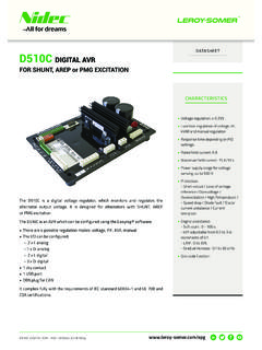
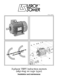
Transcription of Pages 01 et 03 ‹ 05/GB - Leroy-Somer
1 FMV 2107/FMV 2307 Digital frequency invertersfor induction motorsInstallation and maintenanceR f. 2210 - 033 / a - +10 VFrequencyreference0V0 VExternal tripResetForwardReverseB8B9B10SB4KA1B1 Analogue outputsB2 MProgrammingb5 = 1b9 = 1b20 = 0b50 = 18883 Frequency invertersFMV 2107 FMV 2307 NOTELEROY-SOMER reserves the right to modify its product characteristics at any time to incorporate the latesttechnological developments. The information contained in this document may therefore be changed without prior warning. Leroy-Somer gives no contractual guarantee whatsoever concerning the information published in this document andcannot be held responsible for any errors it may contain, nor for any damage arising from its use. CAUTIONFor the user's own safety, this frequency inverter must be connected to an approved earth (Bterminal).
2 Power electronic equipment such as speed controllers, frequency inverters, soft starters, and inverters cannot be used ascircuit-breaking or isolating devices as specified in standard EN 60204 - 1, section an accidental start of the installation represents a risk for personnel or the machinery to be driven, it is imperative to supply theequipment via an isolating device and a circuit-breaking device (power contactor) controllable by an external safety system(emergency stop, fault detector). The frequency inverter is fitted with safety devices which can stop the frequency inverter in the event of faults or even stop themotor. The motor itself can be jammed by mechanical means. Finally, voltage fluctuations, and particularly power cuts, can alsocause the starter to switch removal of the cause of the shutdown can lead to restarting, with consequent hazard for certain machines or such cases, it is essential that the user takes appropriate precautions against restarting when the motor makes anunscheduled equipment meets with existing construction standards.
3 Nonetheless it may cause interference, and the user is responsiblefor carrying out the appropriate action to eliminate such interference. The frequency inverter is designed to power a motor over and above its rated speed (up to 19 times with some settings). If the motor is not mechanically capable of operating at such speeds, the user risks serious damage arising from mechanicaldeterioration of the programming a high speed, it is essential that the user ensures that the motor can tolerate declines all responsibility in the event of the above recommendations not being any intervention, whether to do with the electrics or the mechanics of the installation or machine : - ensure that the power to the inverter has been switched off (fused isolator or circuit-breaker) and locked wait 7 minutes before working on the associated frequency inverter,- indicates sections in this manual relating to the safety of manual describes how to commission FMV 2107 and FMV 2307 digital technology frequency inverters.
4 Itgives details of all the procedures which should be adopted when working on the inverter and showsextension 2107/ FMV 2307 Brakeparallel shafthelical 2000 ORTHOBLOC 2000 PLANIBLOC 2000 Variablevoltage andfrequencyInduction motorGearboxesOptions Communication 4 quadrant options R - FMVH oisting optionsL - FMVL - FMV *Parameter settingRS 232 / RS 485interface+FN 350 - FN 351 Serial link Motor choke options Standard extensions 888 FMV 2107888 FMV 2307 SELF - MCusing PEGASE * PC* Available at a later dateRS232RS485LS - RS232/485 RFI filter options4 Frequency invertersFMV 2107 FMV 2307 FMV 2107 refers to frequency inverters - Power supply 200 to 240V single phase, range to 2307 refers to frequency inverters - Power supply 200 to 240V 3-phase, range to , - Power supply 380 to 480V 3-phase, range to invertersFMV 2107 FMV 2307 CONTENTSP ages1 - GENERAL - General operating - Product - 7 to - Environmental - Weight and - MECHANICAL - Checks on - Installation - Installing the - Through-panel - - Power terminal blocks.
5 - Control terminal 16 - - Electrical and electromagnetic phenomena associated with frequency 18 - - Wiring 19 - - Description of cables and protective devices .. - Special - Connection of the serial - Connection diagrams .. 24 to 274 - - Procedure for using the operator 28 to - Setting up the 31 - - Using terminal C9 : maintain ramp .. - Regulation with integrated PI control - FMV 2107 and FMV 2307 parameters .. 33 to - Guide to 46 to 485 - FAULTS - - Display indication - error - Display indication - inverter - Indication via logic - Flowcharts for locating - - Introduction and - - Measuring voltage, current and - Testing the inverter power 52 - - Testing the inverter isolation and withstand - Spare parts - Product - OPERATING - R - FMV braking - L - FMV lifting interfaces for FMV - Mains filters ( ).
6 - 3-phase motor chokes for attenuation of leakage currents : SELF - - PEGASE parameter-setting - SUMMARY OF 57 - 586 Frequency invertersFMV 2107 FMV 23071 - GENERAL INFORMATION - General operating principleThe synchronous speed (min-1) of a cage induction motoris a function of the number of poles (P) it has and thefrequency (F) of its power supply. These values arerelated by the equation :Thus, changing the frequency (F) also changes thesynchronous speed (N) of a given , changing the frequency without changing thesupply voltage varies the density of magnetic flux in themotor. FMV 2107 / FMV 2307 inverters cause theoutput VOLTAGE and FREQUENCY to varysimultaneously. This allows optimisation of the motortorque curve and prevents 2107 / FMV 2307 inverters power the motor bymeans of a voltage generated from a steady voltage.
7 Voltage modulation is achieved using theprinciple of pulse width modulation ( ).This provides the motor with a current close to a sinewave with few MV motors are designed for use with a frequencyinverter. Their magnetic circuits and windings have beenadapted for use with FMV 2107 / FMV 2307 the motor-inverter unit provides guaranteed torqueperformances in all types of operating conditions (pleaseconsult Leroy-Somer ). - Functional description of the variable speedcontrollerThe variable speed controller comprises : A rectifier for the mains supply voltage, along with asmoothing capacitor to provide a steady voltagewhich depends on the mains supply voltage. An inverter : this voltage supplies power to the 6-transistor inverter (IGBT).
8 The inverter converts voltage to an voltage which is modulated involtage and frequency. Three internal current measurements for the , the inverter output and the braking transistor. An electronic control boardcomprising : the microprocessor, the ASIC circuit whichgenerates PWM and the circuits which amplify thepower control signals. A console for entering parameters, reading data andcontrolling the - Operating diagrams- FMV 2107- FMV 2307N = -- -- -- -- -- -- -- -- -- -- ---120 x FPInternalinterfaceInternalinterfaceI/Oc ontrolMainssupplyASICPWMS witching modepower supplyControlOperatorpanelInverterinterf ace+Control boardPower boardMIGBTDCCTACCTE xternalbrakingresistance(option)Internal interfaceInternalinterfaceI/OcontrolASIC PWMC ontrolOperatorpanelInverterinterface+Con trol boardPower boardMIGBTDCCTACCTE xternalbrakingresistance(option)Mainssup plySwitching modepower - Product designationExamples : FMV 2107 - , FMV 2307 - andFMV 2307 - 2107 : frequency inverter for general applicationsand single phase 200V/240V 2307.
9 Frequency inverter for general applicationsand 3-phase = Rating in = Single phase = 3-phase 200V/240V = 3-phase 380V/440V designation is shown on the identification - - Electrical characteristics7 Frequency invertersFMV 2107 FMV 2307 CharacteristicsFMV 2107 FMV 2307 FMV to to to phase3-phase3-phasesupply 200 to 240V to 10% 200 to 240V to 10%380 to 440V 10% 48 to 56 Hz48 to 62 Hz48 to 62 Hz380 to 480V 10% 58 to 62 current71418510133,54,55,591113 Output current4,37104,37102,12,83,85,67,69,5 Motor power0,751,52,20,751,52,20,751,11,52,234 Output voltage from 0V to supply from 0V to supplyfrom 0V to supply voltagevoltagevoltageMax nbr of power-ups per hour202020 Continuous braking current666 Peak braking current151515 FMV MIl est indispensable de lirela notice avant de raccordercet appareilIt is essential to readthe instructions beforeconnecting the inverterApr s mise hors tension,attendre 5 minutespour toute interventiondans l'appareilAfter switching offthe inverter, wait 5 minutesbefore performingmaintenance or inspectionENTR E / INPUT1 Ph.
10 200 - 240 V50 - 60 HzSerial N :Date :XXXXXXXX/XX/XXSORTIE / OUTPUT3 Ph. 0 - 240 KW4,3 AFMV TLIl est indispensable de lirela notice avant de raccordercet appareilIt is essential to readthe instructions beforeconnecting the inverterApr s mise hors tension,attendre 5 minutespour toute interventiondans l'appareilAfter switching offthe inverter, wait 5 minutesbefore performingmaintenance or inspectionENTR E / INPUT3 Ph. 200 - 240 V50 - 60 HzSerial N :Date :XXXXXXXX/XX/XXSORTIE / OUTPUT3 Ph. 0 - 240 KW4,3 AFMV TIl est indispensable de lirela notice avant de raccordercet appareilIt is essential to readthe instructions beforeconnecting the inverterApr s mise hors tension,attendre 5 minutespour toute interventiondans l'appareilAfter switching offthe inverter, wait 5 minutesbefore performingmaintenance or inspectionENTR E / INPUT3 Ph.