Transcription of Papermaking PAPERMACHINE – PRESSING 1. INTRODUCTION
1 1 Papermaking PAPERMACHINE PRESSING 1. INTRODUCTION The paper web formed on the wire part or the forming section passes onto the press section. PRESSING of the web on the paper machine follows entering of wet web through the nip of two rolls running under pressure . Under the effect of pressure between the two rolls further water removal of paper is obtained and its compactness and strength is increased. The PRESSING operation is important for the capacity and economy of a paper machine and has great influence on paper quality. It determines the dryness of the sheet entering the dryer section. It has a major impact on the structure and runnability of the paper and thus the operating efficiency of the machine (Wahlstrom, 1969).
2 The dewatering capacity of a press section and the properties of paper depend on the design and the number of nips. The risk of web breaks is determined by the general design of press section and the arrangement of open draws if any. A modern press section should fulfill the following requirements: - The highest possible dryness to be obtained with least number of nips. - PRESSING must not impair paper quality. - The press section should be a compact, simple and rigid structure. - Quick felt, fabric and roll changes must be possible. High dryness after the press is required to reduce steam consumption. Removal of water in the dryer section through evaporation is 7-10 times costlier than on presses and 60-70 times costlier than the wire part, though this depends to a great deal on power and steam costs and the efficiency of heat utilization.
3 Dryness of web in the press part varies generally in the range of 15-21% to 35-55% depending on the grade being manufactured and the efficiency of the wet end operation. By using a high pressure and longer nip time it is theoretically possible to get a dryness of web up to 65%. This is the limit of dryness on the presses because 35% water is necessary for wetting of fibres. It is not possible to remove this water by PRESSING without damaging the structure of the fibres. Practical limit of dryness on the press section is 35-55% for different papers (Kocurek, Smook). 2 PRESSING has two major objectives. The first is to remove water from the web, up to a consistency of 40-45%. The second is to consolidate the web, to bring fibres into close contact for bonding.
4 A simple single press nip is shown schematically in below. The web is squeezed between a solid roll and a felt supported by a perforated roll. The water is expelled into the felt and then into the holes of the perforated roll. The latter may be a suction roll. Suction is applied over the PRESSING zone, and when the roll rotates past this suction zone, the water is released to fly out into trays. Grooved or blind-drilled rolls may also fill this same purpose, as shown below. Figure 1 3 Figure: Scale drawing of the press nip. Figure: Felt and the roll surfaces. 4 2. Theory Figure: Nip phases of wet PRESSING (Pandey, 1983). The above represents the transversal flow press-nip defined by two solid rolls with paper and felt passing the nip. Both contain sufficient amount of water to reach saturation before the mid-nip.
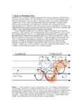
5 The geometric configuration, 5 pressure distribution curves, water transfer mechanism and thickness curves for paper and felt are shown for the nip. The nip has been divided into four phases, Phase-1. starts at the entrance of the nip where the pressure curve begins and lasts until the paper has become saturated. The felt is shown unsaturated in phase 1. Phase-2. extends from the point of saturation to the mid-nip or more accurately to the maximum point of the total nip pressure curve. In this phase felt also reaches saturation. Phase-3. extends from the maximum point of the nip curve to the point of maximum paper dryness. This point corresponds to the maximum of the paper structure, pressure curve and zero hydraulic pressure in the paper.
6 In this expanding part of the nip the felt passes zero hydraulic pressure and becomes unsaturated. Phase-4 covers the point where the paper starts to expand and becomes unsaturated. The felt is unsaturated through this whole phase and expands continuously. The total nip pressure curve is divided into a fluid pressure component and a fibre structure pressure component. The sum of these two components is equal to the total pressure . As the felt has much lower flow resistance than paper the fluid component is much lower in the felt than in paper. The fluid pressure component in the felt is dependant on incoming felt moisture and the amount of water being transferred from the paper to the felt. The proportion of the hydraulic pressure and the pressure in the structure will vary along the nip and through the thickness of the felt and the paper.
7 Hydraulic pressure in the area of paper facing the felt is almost identical to the total hydraulic pressure in the felt. Hydraulic pressure will then grow with the distance from the felt surface and be the highest at the roll. This means that the forces compressing the fibre structure will be largest close to the felt. pressure gradients therefore, exist both in machine as well as perpendicular direction to the sheet and felt. In addition to the pressure curve, area is indicated in the figure above to show the type of mechanism acting in different parts of the nip. This includes the flow of water through compression, two phase flow through capillary forces and the two phase flow through compression and expansion.
8 6 Phase-1. The total pressure of the sheet increases through compression. In this phase air is expelled out of both paper and felt and there is no hydraulic pressure at this point. Felt and paper are both unsaturated and transfer of water can only occur through capillary forces or two phase flow. Very little change in the dryness of the paper in this phase and all the forces are taken by the compression of fibre structure. Phase-2. Hydraulic pressure increases squeezing water from paper to felt. In this phase paper and felt are saturated. Hydraulic pressure is generated resulting in the flow of water from the felt into the receptacles under the felt. Compression force acting on the fibre and the felt structure increases through the whole of phase 2.
9 fluid pressure in the felt and paper reaches maximum ahead of mid-nip. In phase 2 water is flowing out of the system through compression. Before the felt is saturated, there are capillary forces promoting water transfer from paper to felt. Phase-3. The total pressure curve decreases. The fibre structure pressure increases to a maximum point which is also the point of maximum paper dryness, corresponding to the point where fluid pressure in the paper is zero. This means that paper is getting dryer after the mid-nip as long as there is a hydraulic pressure gradient between the paper and felt. As the phase 3 is expanding portion of the nip and paper in this phase gets still further compressed, the felt must take up all compression.
10 Owing to some lateral flow of water through the nip the felt is saturated through a small part of phase 3 corresponding approximately to the felt forcing air and water to enter from underneath through the fabric or grooves. Phase-4 Both paper and felt are exposed in this phase and the paper becomes unsaturated. A negative pressure is created in both the structures. Compressive forces on the fibre structure and felt are larger than total pressure . In this phase it must be assumed that air will enter for the same reason as air would enter the felt in phase 3. However, the vacuum due to the expansion will be larger in the paper than in the felt creating a two phase of air and water into the felt and from felt to paper. In addition capillary forces will act within and between paper and the felt into this phase system.