Transcription of Part 1 General - GE Industrial
1 part 1 ScopeProvide a complete standby [utility parallel] digital power control and distribution system to automatically start and parallel engine generator sets, rated kW Vac, at pF for a three phase, 4[3] wire, 60 [50] Hz Switchgear lineup shall be a complete free-standing assembly, containing the necessary number of the control and distribution sections, including selected optional Reference Standards Generator Paralleling Control Switchgear and all related components shall be designed, manufacturedand tested in accordance with the latest edition of the following applicable National Standards Institute, Inc. (ANSI) Metal-Enclosed Low-Voltage Power Circuit Breaker Switchgear Testing of Metal-Enclosed Low-Voltage Power Circuit Breaker Switchgear Fire Protection Association (NFPA)NFPA - 70 National Electrical Code NFPA - 99 Essential Electrical Systems for Health Care Facilities NFPA - 110 Standard for Emergency and Standby Power Laboratories, Inc.
2 (UL)UL 1558 Switchgear AssembliesUL 891 SwitchboardsUL 508A Control Electrical Manufacturers Association (NEMA)NEMA SG-5 Power Switchgear Standards Organization (ISO)ISO 9001:2000 Guide Specification Standby/Utility Parallel Power Generator SystemsGECritical Power2 Digital Commander Guide Form | Quality Assurance A. Manufacturer s Qualifications: 1. The equipment shall be the product of a manufacturer who has produced this type of equipment for at least 25 years. The manufacturer must be certified under ISO 9001. B. Site Conditions: 1. Altitude: up to 5000 feet above mean sea level 2. Relative Humidity: 100 % maximum, continuous, non-condensing 3. Ambient temperature range: -20 to 105 degree Submittals A. Upon receipt of purchase order, manufacturer shall provide six (6) submittals for approval within thirty (30) working days after receipt of an order, that shall include the following: 1.
3 Project Summary 2. Project Architecture a. Distribution SwitchgearEnclosure information 1. UL standard 2. Bus configuration 3. Cable/lug information b. Low Voltage Controls 1. Digital Commander control components c. Master System Control d. Generator Control e. Utility Control 3. Sequence of Operations a. Description of hardwire interlocks b. Automatic method of operation c. Test w/ Load and Test w/out load d. Manual Operation e. Generator optimization f. Load controls3 Digital Commander Guide Form | 4. HMI touchscreen menus a.
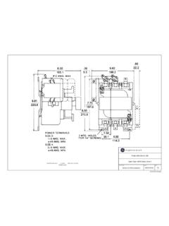
4 Screen Header and Sidebar Information b. Icon legend c. Sample of each operator screen including 1. System mimic 2. System controls 3. Load controls 4. Generator Optimization 5. Metering 6. Maintenance 5. Detailed Bill of Materials 6. Drawings a. Mechanical Drawings: 1. Dimensional plans and elevations, with front and side views, and other pertinent elevation views 2. Conduit entrance locations and dimensions within all assemblies for both bottom and top entrance 3. Door details. 4. Circuit Breaker ratings.
5 5. Weight of equipment (lbs.) 6. Assembly ratings including: i. Bus Bracing (kA) ii. Short circuit rating ( kAIC) iii. System Voltage (V) iv. Continuous current rating (A) b. Electrical Drawings: 1. Typical AC Three-Line Schematic diagrams with all components cross referenced 2. Typical DC Schematic diagrams with all components cross referenced 3. Typical equipment interconnecting drawings showing terminal points and external device function 7. Major component product data sheets4 Digital Commander Guide Form | 2 General Requirements A. Approved Vendors 1. General Electric (also known as GE, Zenith, GE Critical Power or GE Zenith Controls) Construction A. The enclosures shall be freestanding, floor supported, with front and rear access. Removable lifting eyes shall be supplied for lifting purposes.
6 Adequate number of anchor bolt-holes spaced to place the base in direct contact with the concrete pad when bolted. All doors shall be pan type and be provided with sufficient hinges to support the door and components for minimum deflection and wobbling when opening or closing. Front doors shall be supplied with a lockable handle. All door locks shall be keyed alike to operate from a single key, with one key supplied for each lock. All panel covers are secured with captive screws as necessary. B. An assembly shall be submitted to a degreasing and cleaning process. The finish shall be ANSI-61, light gray, electrostatically charged polyester powder paint process, minimum mils in density. Finish shall be suitable for indoor and outdoor environments. Bus A. Bus shall be silver plated copper and shall have a maximum current density of 1000 A per square inch. B. Main bus shall be rated for [XXXXXA] and have a minimum bracing level and short circuit capacity not less than 100,000 A C.
7 A full size copper neutral bus and a 25% ground bus shall be provided and shall extend the full length of the Wiring/Terminations A. Control wiring 600 V, per UL 1015 or SIS. Use solder-less compression screw type connectors for terminating all wires. Current transformer circuit terminations shall be ring tongue compression type. Other circuits shall be ring tongue compression type where feasible, otherwise they shall be spade type applied with the proper tooling. B. Current transformer circuits are connected through shorting terminal blocks. 5 Digital Commander Guide Form | Power Circuit Breakers A. The generator [utility-tie] and distribution circuit breakers shall be low voltage draw-out, either 3 or 4 pole with interrupting current ratings no less than 100 kAIC (symmetrical) and shall be UL 1066 (ANSI C37) rated. B. The draw-out feature shall provide for connected, test and disconnected positions. In the connected position, the main line and load terminals and all auxiliary control contacts and circuitry shall be connected and the breaker shall be fully operable.
8 In the test position, the breaker auxiliary control contacts and circuitry only shall be connected to permit automatic operation of the complete control system without actually connecting the generator to the main bus. Main and auxiliary control contacts and circuitry shall be completely disconnected in the disconnect position. C. The breaker draw-out mechanism shall be mechanically interlocked with the breaker to permit draw-out operation only when the breaker main contacts are open. D. The generator circuit breakers shall be electrically operated with shunt trip, furnished with electronic trip units with Adjustable Long Delay, Short Delay and Instantaneous over current trips and Ground Fault Alarm only functions, and rated as described on the drawings. E. The distribution circuit breakers shall be electrically operated with shunt trip [ or manually operated] , and furnished with electronic trip units with Adjustable Long Delay, Short Delay and Instantaneous over current [and Ground Fault] trip or alarm functions and rated as described on the drawings.
9 Circuit breaker electronic trip unit shall include instantaneous overcurrent functions on/off feature. [Optional - to provide paralleling with utility functions and overcurrent protection] F. The utility-tie circuit breaker shall be electrically operated with shunt trip, furnished with electronic trip units with Adjustable Long Delay, Short Delay and Instantaneous over current and Ground Fault trip functions, and rated as described on the drawings. The utility tie circuit breaker shall be equipped with a control switch with breaker position indicating lights, all mounted on a section door. G. Required breaker design and accessories: 1. Draw-out structure (Cassette) 2. Shutter 3. Electrically operated (EO): 120 Vac Charge, 24 Vdc Shunt trip 4. Breaker Push-To-Close Button 5. Breaker Push-To-Open Button 6. Auxiliary contact (source breakers): 4a/4b (Source Breakers), minimum 2a/2b (Distribution breakers) 7.
10 Truck-Operated Contact (TOC) for draw-out type breaker: 1a/1b [2a/2b] 8. Bell-Alarm Lockout (BAL) 9. Trip unit / Generator Breaker: Released-Energy-Let-Through (RELT) Technology with LSIGA (Ground Fault Alarm - Generator) 10. Trip unit / Main and Distribution Breakers: Released-Energy-Let-Through (RELT) Technology with LSIG (Ground Fault Trip) 11. Pushbutton cover (E/O and source breakers) 12. Mechanical Counter (Source Breakers) 13. Under Voltage Trip Coil (UVT) CoGen Breaker 14. Padlock provision 15. Advanced Metering/Modbus (power) communication 16. Zone Selective Interlock (ZSI) [CM Must include 1 TIM-1 module for GE Breakers]6 Digital Commander Guide Form | Control and Power Components A. Current Transformers - Current transformers are furnished with VA burden ratings suitable to supply the metering, protective devices and electronic governor without affecting their accuracy.