Transcription of Part 2 Filters
1 - 1 - filter CIRCUITS Introduction Circuits with a response that depends upon the frequency of the input voltage are known as Filters . filter circuits can be used to perform a number of important functions in a system. Although Filters can be made from inductors, resistors and capacitors most filter circuits are based upon op-amps, resistors and capacitors. filter types and characteristics A filter is a circuit whose transfer function, that is the ratio of its output to its input, depends upon frequency. There are three broad categories of filter which are widely used: Low-pass Filters allow any input at a frequency below a characteristic frequency to pass to its output unattenuated or even amplified.
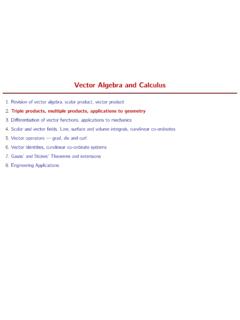
2 High-pass Filters allow signals above a characteristic frequency to pass unattenuated or even amplified. Band-pass Filters allow frequencies in a particular range to pass unattenuated or even amplified. - 2 - The transfer function of a circuit is usually expressed on a logarithmic scale in decibels, and since the fundamental quantity of interest is power, a filter is characterised by The symbols and Bode diagrams for the ideal transfer functions for these Filters are shown in Figure (18) Figure 18 The symbols and characteristics of three types of Filters - 3 - Applications of Filters Circuits that attenuate undesirable frequency components of an input signal can fulfil three important functions.
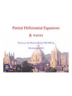
3 Anti-Alias Filtering Figure 19: A schematic diagram showing signals of two different frequencies which are indistinguishable when they are sampled at a finite number of points. Aliasing is a phenomenon that arises because all digital systems can only represent a signal at particular instances in time. An important consequence of this sampling is seen in Figure (19). This shows two different signals sampled at the same rate, with the same time interval between each sample. Although it is clear that the input signals are at different frequencies, it is equally clear that the four data points acquired by the digital system are the same.
4 To the digital system these two signals are - 4 - therefore indistinguishable. The conditions necessary to avoid this confusion are stated formally in the sampling theorem: If the continuous input signal contains no frequency components higher than , then it can be completely recovered without distortion if it is sampled at the rate of at least 2 samples per second However, input signals can potentially contain frequency components at any frequency. Thus before a signal is sampled into a digital system the designer must determine the maximum frequency, , in the input signal that will contain useful information.
5 A filter must then be designed which attenuates all frequencies above , prior to sampling by the ADC at a frequency of at least 2*. This type of anti-aliasing filter must be present in any well designed system that includes an analogue to digital converter. Noise Rejection Ohms law is based upon the average behaviour of the electrons flowing through a resistor and it predicts the average current that will flow when a particular voltage difference is applied to a resistor. However, the behaviour of electrons is similar to atoms in a gas and the random thermal agitation of the electrons leads to fluctuations in the instantaneous current flow.
6 These random fluctuations in the current, and hence the voltage, are known as noise. Noise is generated within the components of a circuit and contains components at all frequencies. This means that a circuit that - 5 - responds to a smaller frequency range will have less noise in its output. Filters that limit the range of frequencies in their output are therefore useful for limiting the amount of noise. The quality of a signal in the presence of noise is most often specified by the signal-to-noise ratio (SNR) which is where is the rms value of the signal and is the rms value of the noise.
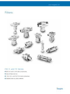
7 The effectiveness of using Filters to reduce noise is demonstrated in Figure (20). In this case the original signal that is the input to the filter looks like noise, with a slowly varying mean value that hints at the presence of a low frequency component in the signal. When this signal is filtered using a low-pass filter with a characteristic frequency of 100Hz, it becomes clear that there is a small 10Hz signal buried in the noise. Thus despite an original signal-to-noise ratio of it is possible to recover a signal by filtering out the noise.
8 - 6 - Figure 20: The input signal at the top is difficult to distinguish from noise. This is in sharp contrast to the filter output at the bottom that clearly shows a 10Hz signal. Interference Rejection Although interference can be minimised by careful design it is sometimes necessary to also employ Filters . Often the dominant source of interference is the mains power supply and so it can be necessary to use a filter to attenuate the frequency of the local mains power supply, 50 Hz in the UK, and/or some of its harmonics. - 7 - Figure 21 At the top of the figure is a 500Hz input signal with a 10Hz source of interference which is an order of magnitude larger.
9 After filtering with a band-pass filter the interference is dramatically reduced. A simple example of the use of a band-pass filter to remove interference is shown in Figure (21). In this example the voltage signal at a particular point in the system consists of a small signal at 500Hz and a strong source of interference at 10Hz. Using a band-pass filter with a characteristic frequency of 500Hz it is possible to reduce the amount of interference by a factor of 400 without attenuating the signal at 500Hz. - 8 - Passive Filters In principle, Filters can be made from passive components, that is resistors, capacitors and inductors.
10 However, at low frequencies, typically below 100 MHz, the inductors required to generate a reasonable impedance are bulky. Furthermore, they will include significant resistance that will limit the performance of any filter . Most Filters therefore contain resistors and capacitors. Figure 22: Various passive low-pass Filters . The simplest passive filter can be created using a resistor and capacitor. An example of this type of circuit designed to be a low-pass filter is shown in Figure (22 (a)). The response of this type of filter , is which can be re-written as - 9 - to show that the circuit attenuates high frequency signals.