Transcription of Part Design Guidelines for Injection Molded Thermoplastics
1 Part Design Guidelines for Injection Molded ThermoplasticsRecommended by our Computer-Aided Engineering Support Your Plastic PartWhen designing parts for Injection molding , the manufacturing process is an importantconsideration. Injection molding is a process in which solid thermoplastic resin pellets are melted, injected into a mold, and then cooled back to a solid state in a new form. During both the Injection and cooling stages of the manufacturing process, there are several factors that may affect the quality of the final product and the repeatability of the manufacturing process. Although it is not always possible to follow all recommendations, outlined on the following pages are some of the most fundamental Guidelines when designing parts for Injection Maximum rib thickness should be to of the nominal wall to avoid creating areas of sink.
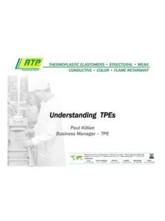
2 To avoid thin sections of steel in your mold, the distance between ribs should be at least two and a half times the nominal wall thickness. Ribs should have a draft angle of at least per side in order to accommodate easier ejection from the mold. Maximum rib height should be no greater than three times the nominal wall thickness in order to avoid large variations in wall thickness. Balance ribs on both sides of the nominal wall to avoid non-uniform shrink that can lead to desired radii of adjoining walls are related to wall sharp corners where a boss meets the wall can help reduce stress addition to rib thickness and height, the draft angle should also be taken into consideration. See the Draft Angle section for more An inside radius should be at least 50 percent of the nominal wall thickness.
3 An outside radius should be the nominal wall thickness plus the inside radius (150 percent of nominal wall). Sharp corners at the base of bosses and ribs can be stress concentrators. The edge where a boss meets the nominal wall should be radiused to reduce the sharp corner without increasing the wall thickness enough that it creates a sink problem. The radius at the base of a boss should be of the nominal wall with a minimum radius of .Inside Radius > T/2 Thickness = TOutside RadiusEquals Inside Radius + TRadius Baseof bossr=T/4( minimum)PlaneRadius Baseof bossr=T/4( minimum) X T X T X T / DRAFT T 21 For plastic parts, a gradual change in wall thickness is recommended to reduce stress concentration and other potential Recommendations:Wall Thickness Maintain a wall thickness of less than 5mm because thick walls can lead to long cycle times and poor mechanical properties.
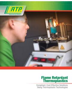
4 Avoid large variations in wall thicknesses in order to simplify flow pattern and minimize variations in shrinkage that can lead to warpage. Avoid abrupt changes in wall thickness, as this can create stress concentration areas that may reduce a part s impact strength. Wall thickness changes should have transition zones that reduce the possibility of stress concentrations, sinks, voids, and warp. Avoid gating near an area with a large variation in wall thickness because hesitation and race tracking can create non-uniform flow and R= *T T/2 to T/3 Rib Boss R=T/4 ( min) Connecting Rib Strengthening Gusset Nominal Wall T > 2T R=T/2 2T 4T >2T >2T T/2 Thick SectionCore OutThick sectionRecommendedNot RecommendedMetal parts are often designed with thick walls, while plastic parts should ideally maintain uniform wall thickness for uniform flow and less shrinkage.
5 Thick SectionCore OutThick sectionRecommendedNot RecommendedTypical Metal Design :Thick SectionCore OutThick sectionRecommendedNot RecommendedPrefered Plastic Versus Semi-Crystalline Materials:Amorphous MaterialsIn amorphous materials, molecules are randomly oriented and intertwined. Polymer molecules have no ordered structure. These materials have no identifiable melting point but progressively soften through a broad temperature range. Unfilled amorphous materials are typically isotropic, shrinking equally in the flow and transverse directions. Even fiber-filled amorphous materials typically have low shrink and good dimensional materialsSemi-crystalline materials have areas of random molecule orientation but they also contain regions where molecules pack together to form ordered crystalline structures.
6 These materials have a sharp melting point and are typically solvent resistant. These materials can be anisotropic which means they shrink differently in the flow versus transverse directions. Typical Shrinkage Values for Amorphous MaterialsBased on a 1/8 ( ) section using ASTM D 955 MaterialMold Shrinkage ( )Unfilled Acrylonitrile Butadiene Styrene (ABS) Polycarbonate (PC) Polysulfone (PSU) Polyetherimide (PEI) Acrylic (PMMA) Shrinkage Values for Semi-Crystalline MaterialsBased on a 1/8 ( ) section using ASTM D 955 MaterialMold Shrinkage ( )Unfilled Polypropylene (PP) - filled Polypropylene (PP) - Density Polyethylene (HDPE) - Nylon Nylon 6 (POM) Design of boss dimensions and part ratios is helpful in optimizing a modest draft angle on walls, bosses, ribs, and other features, is helpful to remove the part from the threads are designed differently than metal threads with larger crests and depth of Stand-alone bosses should be designed following the Design Guidelines for ribs (see more information under the Ribs section).
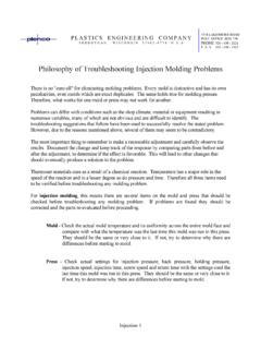
7 Use connecting ribs and/or supporting gussets if possible to stiffen structural parts. Connecting ribs should be times the nominal wall thickness at their base to avoid sink. To maintain uniform wall thickness, bosses should be cored to the bottom of the Angle Design parts with a minimum of per side draft in order to accommodate easier ejection from the threads used for joining parts can be machined or Molded -in. When designing Molded -in threads, avoid feathered edges and include radiused roots in order to minimize stress concentrations and to keep the walls uniform. Sharp edges can be stress concentrators in plastic parts. Thread designs should consider X internal X thickness of adjoining walls, maximum X the height of the outside wall All inside - Xoutside radius / in ( mm) PP2 Walls Drafted / /sideNo DraftDraft Angle21 Walls Drafted / /sideNo DraftDraft Angle21 Walls Drafted / /sideNo DraftDraft 107 CC Design Data(75 Degrees F) - - PSIM olded Tensile BarsApproximate LongitudinalOrientation BehaviorApproximate TransverseOrientation BehaviorMaterial Data Assistance:RTP Company can provide guidance and material data for customers doing their own CAE analysis.
8 We offer in-house testing and curve-fitting for both standard and custom materials. Your custom materials data will be processed with RTP Company s strict confidentiality procedures. We have over 400 materials characterized for flow simulation and if your material is not already characterized, we can test it for sheet properties are generated on carefully designed Molded specimens, and these properties do not always reflect the performance of an actual part, often due to fiber orientation. RTP Company can assist by providing data on how materials perform in different directions, as shown on this stress/strain Services from RTP Company RTP Company has a team of experienced Computer-Aided Engineering (CAE) analysts who can assist in providing material data, structural analysis, as well as filling and warpage analyses utilizing Moldflow.
9 We offer product Design review and consultation of the following: Innovative thermoplastic solutions that optimize your Design and cut processing costs Injection molding analysis Structural analysis (FEA) Plastic part Design assistance Mold Design assistance Structural failure consultation Composite materials Design assistance and education Quick mechanical structural Design review Product testing recommendation(case study) Speaker Mount for Casino Gaming System When WMS Gaming, Inc., and their molder, Top Die Plastics, Inc., collaborated to develop a premium sound system for a casino gaming device, they wanted to use a single material that could provide strength, electrostatic dissipation, and flame retardant properties. Engineers from RTP Company recommended an RTP 300 Series static dissipative compound; however, the requirement of both Conductive and Flame Retardant additives was a concern, as the combination of the two raises the melt formulation adjustments were made to create a higher flow grade, WMS Gaming feared that they would still need to create an expensive and time-consuming three-plate mold for consistent part filling.
10 Instead, RTP Company s Computer-Aided Engineering team performed a mold-flow analysis to model the material s characteristics with the existing mold plan. Successive iterations of the molding analysis tested alternate runner sizes and gate locations to optimize the mold Design . Performing such an analysis before cutting steel not only spared expense, but also kept the project on schedule, stated Norm Wurz, of WMS Gaming. RTP Company increased the value of our product by providing support to customize it specifically to meet our needs. Key DefinitionsAmorphous PolymerA polymer characterized by random entangled polymer chains. Generally amorphous materials have lower shrink and better dimensional stability than semi-crystalline the same in all directions. This term might be applied to shrinkage for materials that shrink differently in the direction of flow than they do across the flow direction.