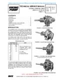
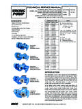
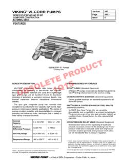
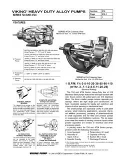
Transcription of PARTS ACCESSORIES: Section 610 HELICAL GEAR REDUCERS …
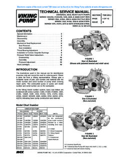
1 gear Ratio Range: (varies by reducer size) :1 to :1 Output Speeds (with 1750 rpm input)950 to 220 rpmReducer Horsepower HP (.1 kW) to HP ( kW)Universal MountingEach size has one or more mounting brackets which match the reducer s output (slow speed) shaft height to the drive shaft height on one or more Viking pumps. Adjustment slots on the brackets allow you to swivel the reducer s input (high speed) shaft height to adapt to a variety of motors or other prime movers. These mounting brackets assure no radial load on the reducer , drive or driven shafts. A Size reducer (mounting bracket on input side) B Size reducer (mounting bracket on output side) C Size reducer (mounting bracket on output side)THREE SIZES AVAILABLEV iking s HELICAL gear REDUCERS are available in three basic sizes, each size offering several gear , Robust DesignAll ratios are fully interchangeable in each gearbox.
2 All three REDUCERS contain a hardened steel pinion and gear supported by precision ball bearings. A Unit of IDEX Corporation Cedar Falls, IA A, B & CPARTS & ACCESSORIES: HELICAL gear REDUCERSSELECTING THE CORRECT VIKING HELICAL gear REDUCER1. Determine the actual horsepower requirements of the application from the pump curve or specifications for other driven Determine the equivalent horsepower for the application by multiplying the actual horsepower to be transmitted by the appropriate service factor, which can be obtained from the Service Factor Table on page 4. This service factor takes into account the length of service per day, the load classification (uniform, moderate shock, heavy shock), and the type of drive. A table of driven load classifications is included to help you determine the service factor to Find the reducer from the Horsepower Tables on pages 4 and 5 which most closely matches your speed requirements.
3 Make sure the equivalent horsepower (kW) for a given input speed and ratio is less than or equal to the maximum recommended horsepower (kW) shown in the chart on the MAXIMUM reducer HP / KW Select the correct reducer bracket to match the driven load s shaft height. For Viking Pumps, refer to the table shaft Center Height for Common Viking Pumps on the following page, but always verify shaft height on the actual pump s dimensional drawing. For certain pumps, a set of Pump and reducer Mounting Pads are required to match the pump shaft height to the reducer shaft height, as listed below: For General Purpose L, LQ and LL pumps with 6 shaft height, use Pump and reducer Mounting Pads, Part No. 2-773-008-200 (2-Req d) under the 5-1/2 reducer bracket for B reducer units. For Heavy Duty L, LQ, LL and LS pumps with 7 shaft height, use Pump and reducer Mounting Pads, Part No.
4 2-773-011-200 (2-Req d) under the pump, and the 7-3/4 reducer bracket for C reducer units. For Q and QS Heavy Duty pumps with 8-3/4 shaft height, use Pump and reducer Mounting Pads, Part No. 2-773-010-200 (2-Req d) under the 7-3/4 reducer bracket for C reducer units. For M Heavy Duty pumps with 10 shaft height, use Pump and reducer Mounting Pads, Part No. 2-773-009-200 (2-Req d), and the 9-1/2 reducer bracket for C reducer Check the Specifications table to ensure that the shaft center height of your driver falls within the Input shaft Center Height Min / Max :A Viking K124A requires a 7 HP driver at 420 rpm to deliver the desired output of 40 gpm at 200 psi on 100 SSU fluid (from the pump curve), and is driven 24 hours per day. Using the Service Factor table, multiply the service factor (in this case, ) times the horsepower required (7 HP) for a reducer horsepower requirement of at the Specifications Table, using a 1750 rpm motor, the desired 420 RPM output speed requires a reducer gear ratio of about :1.
5 Reviewing the Horsepower tables, the A size reducer s Maximum reducer HP at is insufficient. The B size reducer offers a Maximum reducer HP of 11 HP, which exceeds the HP required, so select the B reducer with :1 ratio, P/N the pump has a 5-1/2 shaft height, select the B reducer bracket with matching output shaft height, P/N 2-074-008-100. Check that the driver shaft height is within the min/max input shaft height range ( to ) of this reducer bracket. The selected driver, a 213T frame motor with 5-1/4 shaft height, is within the allowable range. A Unit of IDEX Corporation Cedar Falls, IA A, B & CPARTS & ACCESSORIES: HELICAL gear REDUCERSSPECIFICATIONS: HELICAL gear REDUCERS AND BRACKETSR educer SizeViking reducer Part RatioOutput Speeds (RPM) Wt. ( Kg)1 Viking reducer Bracket Part shaft Center Height (In.)Approx. Shipping Wt. ( Kg)@ 950 RPM Input@ 1450 RPM Input@1150 RPM Input@1750 RPM :142064052078021 / / :152078064095037 / / :13505204206402-074-008-1005-1/210 / :11902802303502-074-007-100711 / :142064052078094 / / :12303502804202-074-012-1009-1/224 / :11201801452201.
6 Any B size reducer bracket may be used with any B size reducer , and any C size reducer bracket may be used with any C size Shows adjustment range of input (high speed) shaft , allowing the gear reducer to be matched to various drivers. Range will change when using Pump and reducer Mounting CENTER HEIGHT FOR COMMON VIKING PUMPSPump SizeShaft Centerline Height (inches)Series 32, 432, 34 Series 124A/AE/E, 4124A/AE/B, 224A, 4224A/B, 324A, 4324A, 8124A, 4624B, 4924A, 123A, 4123A, 223A, 4223A, 323A, 4323A, 8123A, 127A, 4127A, 227A, 4227A, 327A, 4327A, 8127A, 157B, 4157B, 257B, 4257B, 724, 4724, 126A, 4126A, 226A, 4226AC, F, FH1-5/8G, GG2-3/42-3/41H, HJ, HL2-3/43-1/2AS, AK, AL5-1/4K, KK4-5/85-1/2L, LQ, LL, LS67Q, QS7-3/48-3/4M9-1/210N9-1/29-1/2R, RS13-1/41. G724 and G4724 are 2 A Unit of IDEX Corporation Cedar Falls, IA A, B & CPARTS & ACCESSORIES: HELICAL gear REDUCERSSERVICE FACTOR TABLEPOWERSOURCE 1,3 CLASSIFICATION OF DRIVEN LOAD 2,3 INTERMITTENT UP TO 3 HOURS PER DAY8 TO 10 HOURS PER D AY24 HOURS PER D AYElectric Motor, Steam Turbine, or Hydraulic Internal Combustion For applications driven by single cylinder engines, refer to factory for other service Rotary Pump applications are classified as Uniform Use of belt or chain type drives to either reducer input or output shaft is not LOAD CLASSIFICATIONS(Excerpted from AGMA Information Sheet 922-A96 1996)Key: U = Uniform Load; M = Moderate Shock.
7 H = Heavy ShockAPPLICATIONLOAD CLASSIFICATIONAPPLICATIONLOAD CLASSIFICATIONP umps, Rotary and CentrifugalUFans, Cooling TowerMPumps, ReciprocatingMFeeders, Apron, Belt, ScrewUAgitatorsUFeeders, ReciprocatingMBlowersUGeneratorsUCompres sors, Centrifugal & LobeUHammer MillsMCompressors, ReciprocatingMMachine ToolsMCranes and HoistsMMills, RotaryMCrushers, Ore and StoneHMixers, Concrete, Drum TypeMElevatorsMPrinting PressesUFans, Centrifugal, Forced DraftUSewage Disposal Bar ScreensUVIKING A SIZE HELICAL reducer HORSEPOWER TABLEHIGH SPEED shaft INPUT RPM 1 VIKING gear reducer RATIOS A to 1 to to to 11750780640520420 Low Speed shaft / / / / reducer HP / KW1450640520420350 Low Speed shaft / / / / reducer HP / KW1150520420350280 Low Speed shaft / / / / reducer HP / KW950420350280230 Low Speed shaft / / / / reducer HP / KW870390320260210 Low Speed shaft / / / / reducer HP / KW720320260210175 Low Speed shaft / / / / reducer HP / KW A Unit of IDEX Corporation Cedar Falls, IA A, B & CPARTS & ACCESSORIES.
8 HELICAL gear REDUCERSVIKING B SIZE HELICAL reducer HORSEPOWER TABLEHIGH SPEED shaft INPUT RPM 1 VIKING gear reducer RATIOS B to 1 to to to to to to to 11750950780640520420350280230 Low Speed shaft / / / / / / / / reducer HP / KW1450780640520420350280230190 Low Speed shaft / / / / / / / / reducer HP / KW1150640520420350280230190155 Low Speed shaft / / / / / / / / reducer HP / KW950520420350280230190155125 Low Speed shaft / / / / / / / / reducer HP / KW870470390320260210175140115 Low Speed shaft / / / / / / / / reducer HP / KW72039032026021017514011595 Low Speed shaft / / / / / / / / reducer HP / KWVIKING C SIZE HELICAL reducer HORSEPOWER TABLEHIGH SPEED shaft INPUT RPM 1 VIKING gear reducer RATIOS C to 1 to to to to to to 11750780640520420350280220 Low Speed shaft / / / / / / / reducer HP / KW1450640520420350280230180 Low Speed shaft / / / / / / / reducer HP / KW1150520420350280230190145 Low Speed shaft / / / / / / / reducer HP / KW950420350280230190155120 Low Speed shaft / / / / / / / reducer HP / KW870400320260215175140110 Low Speed shaft / / / / / / / reducer HP / KW72033026021517514011590 Low Speed shaft / / / / / / / reducer HP / KW 1.
9 For input speeds higher than 1750 RPM, consult the factory. A Unit of IDEX Corporation Cedar Falls, IA A, B & CPARTS & ACCESSORIES: HELICAL gear REDUCERSDIMENSIONS A SIZE reducer BRACKETDIMENSIONS A SIZE VIKING HELICAL gear MOUNTING HOLES3/8-16 UNC - PLUGBREATHEROIL LEVEL " X .11" " X .11" KEYWAYHIGH SPEED ORINPUT SHAFTLOW SPEED OROUTPUT shaft A Unit of IDEX Corporation Cedar Falls, IA A, B & CPARTS & ACCESSORIES: HELICAL gear REDUCERSDIMENSIONS B SIZE reducer BRACKETDIMENSIONS B SIZE VIKING HELICAL gear reducer A Unit of IDEX Corporation Cedar Falls, IA A, B & CPARTS & ACCESSORIES: HELICAL gear MOUNTING HOLES1/2-13 UNC - " X .18" KEY " X .18" KEYSEATHIGH SPEED ORINPUT SHAFTLOW SPEED OROUTPUT SHAFTDIMENSIONS C SIZE reducer BRACKETDIMENSIONS C SIZE VIKING HELICAL gear reducer A Unit of IDEX Corporation Cedar Falls, IA A, B & CPARTS & ACCESSORIES: HELICAL gear REDUCERSINPUT shaft CENTER HEIGHT MIN/MAX*Viewed from input shaft endB Output shaft center height (Centerline of mounting bracket)H Input shaft center heightSizeMounting Bracket Part shaft Center Height [in.]
10 ]Left HandRight HandInput shaft Center Height [in.]Input shaft Center Height [in.] HAND*LEFT HAND*BBHH A Unit of IDEX Corporation Cedar Falls, IA A, B & CPARTS & ACCESSORIES: HELICAL gear REDUCERSAPPLICATION DATA SHEETCOMPANY _____ DATE _____NAME _____ TITLE _____ADDRESS _____ CITY _____ STATE _____COUNTRY _____ POSTAL CODE _____PHONE _____ FAX _____ EMAIL _____PRIME MOVER( ) Electric Motor; ( ) Gasoline Engine; ( ) Diesel Engine; ( ) Steam Engine; ( ) Turbine;Number of Cylinders _____; Normal Operating Speed _____ RPM;Speed Range: (Min.) _____ RPM; (Max.) _____ RPM;Normal Rating _____ HP at _____ RPM;Maximum Overload Capacity _____ HP at _____ RPM;Special Features _____DRIVEN EQUIPMENTD escription _____Character of Load: ( ) Smooth; ( ) Moderate Shock; ( ) Heavy Shock;Daily Operating Period: ( ) Not to exceed 3 hours; ( ) 8 to 10 hours; ( ) 24 hours;Rotation: ( ) Continuously One Direction; ( ) Reversing Service;Actual Starting Load _____ HP; How Frequent _____Actual Normal Operating Load _____ HP; _____ HP at Min RPM; _____ HP at Max RPM;Actual Max.