Transcription of PARTS MANUAL MANUAL
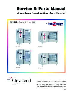
1 PARTS MANUAL . G, SL & B-Series GAS CONVECTION OVENS. G-Series Models SL-Series Models B-Series Models GS/15SC SLGS/12SC SLGS/19SC BGS/12SC. GS/15 CCH SLGS/12 CCH SLGS/19 CCH BGS/22SC. GS/25SC SLGS/22SC SLGS/29SC. GS/25 CCH SLGS/22 CCH SLGS/29 CCH. GB/15SC SLGB/12SC SLGB/19SC. GB/15 CCH SLGB/12 CCH SLGB/19 CCH. GB/25SC SLGB/22SC SLGB/29SC. GB/25 CCH SLGB/22 CCH SLGB/29 CCH. Model GS/15SC Model SLGS/12SC. 1100 Old Honeycutt Road, Fuquay-Varina, NC 27526. Copyright 2014 by Southbend. All rights reserved. Published in the United States of America. MANUAL 1198300 REV 4 (10/14) FULL SIZE. ECN 14-150 GAS CONVECTION OVENS. INFORMATION FULL SIZE GAS CONVECTION OVENS. Replacement PARTS may be ordered either through a Southbend Authorized PARTS Distributor or a Southbend Authorized Service Agency. It is recommended to verify part numbers with a Southbend Authorized PARTS Supplier or the Southbend PARTS /Service Dept.
2 Prior to ordering PARTS . When ordering PARTS , you will need to supply the Model Number, Serial Number, Part Number, Description, Finish, and Electrical Characteristics as applicable to the unit. The serial plate is located on the interior side of the lower front panel, as shown below. INFORMATION. Serial plate (inside cover). PAGE 2 PARTS MANUAL 1198300 REV 4. FULL SIZE GAS CONVECTION OVEN INFORMATION. ELECTRICITY SUPPLY. Convection ovens require connection to a supply of electricity. The appliance, when serviced, must be electrically grounded in accordance with local codes, or in the absence of local codes, with the National Electrical Code, ANSI/NFPA 70, or the Canadian Electrical Code, CSA , as applicable. An electrical diagram is located on the side of the control panel assembly in each unit. (see drawing on page 5). Power Option Power Type # of Ovens Maximum Amps Single-Deck 120/60/1 120 Volts, 60 Hz, Single Phase Double-Deck Single-Deck 208/60/1or3 190-219 Volts, 60 Hz, Single or Three Phase Double-Deck Single-Deck 240/60/1or3 220-240 Volts, 60 Hz, Single or Three Phase Double-Deck Single-Deck 240/50/1or3 208-240 Volts, 50 Hz, Single or Three Phase Double-Deck Ovens ordered with the 120V power option are equipped with one or two power cords with a standard 120V single-phase plug with a ground prong.
3 Single-deck ovens will have one power cord; double-deck ovens will have two. Ovens with other power options have a terminal block on the rear of the oven that must be wired to the power supply. Depending on how the power supply is connected to the terminal block, the oven can operate on either single-phase of three-phase power. INFORMATION. GAS SUPPLY. The serial plate is located inside the lower front panel. It indicates the type of gas the unit is equipped to burn. All Southbend equipment is adjusted at the factory. Check type of gas on serial plate. These models are design-certified for operation on natural or propane gases. For natural gas, the regulator is set to deliver a " pressure to the manifold. For propane gas, it is set to deliver 11". If applicable, the vent line from the gas appliance pressure regulator shall be installed to the outdoors in accordance with local codes, or in the absence of local codes, with the National Fuel Gas Code, ANSI.
4 , Natural Gas Installation Code, , or the Propane Installation Code CAN/CGA- , as applicable. This appliance should be connected ONLY to the type of gas for which it is equipped. A 3/4" NPT line is provided at the rear for the gas connection. An adequate gas supply is imperative. Undersized or low pressure lines will restrict the volume of gas required for satisfactory performance. Fluctuations of more than 25% on natural gas or 10% on propane gas will create problems and affect burner operating characteristics. An adequate gas supply line to the unit should be no smaller than the inside diameter of the pipe from the unit to which it is connected. Purge the supply line to clean out dust, dirt, or other foreign matter before connecting the line to the unit. All pipe joints and connections must be tested thoroughly for gas leaks. Use only soapy water for testing on all gases.
5 NEVER use an open flame to check for gas leaks. All connections must be checked for leaks after the unit has been put into operation. Test pressure should not exceed 1/4" PARTS MANUAL 1198300 REV 4 PAGE 3. INFORMATION FULL SIZE GAS CONVECTION OVENS. Reference chart for unit specific gas type properties: Model Number # of Ovens Total BTU Type of Gas Orifice Size Propane 56. BGS/12 Single-Deck 54,000. Natural Gas 47. Propane 56. BGS/22 Double-Deck 108,000. Natural Gas 47. SLGS/12 Propane 56. SLGB/12 Single-Deck 72,000. Natural Gas 47. SLGS/22 Propane 56. SLGB/22 Double-Deck 144,000. Natural Gas 47. Propane 56. GS/15 . GB/15 Single-Deck 90,000. Natural Gas 47. INFORMATION. Propane 56. GS/25 . GB/25 Double-Deck 180,000. Natural Gas 47. PAGE 4 PARTS MANUAL 1198300 REV 4. FULL SIZE GAS CONVECTION OVENS INFORMATION. CONTROL PANEL ACCESS AND SHUT-OFF SWITCH. To access the control panel components, remove the two thumbs screws at the top and bottom of the control panel and slide the control panel out (see 1ST picture).
6 A wiring diagram for the oven is located on the side of the control panel assembly. When the control panel is slid out, all power to the control panel is cut off by a shut down switch that is located directly inside the opening and below the control panel (see 2ND picture). To re-energize the controls for troubleshooting, pull the plunger on the shut down switch up. To fully remove Control Panel, disconnect temp probe wires and harness connectors prior to pulling up on slide release levers and removing. Accessing Control Panel Components INFORMATION. Accessing Control Panel Components PARTS MANUAL 1198300 REV 4 PAGE 5. PARTS FULL SIZE GAS CONVECTION OVENS. P ARTS. NOTICE. INSTALLATION OF OTHER THAN GENUINE SOUTHBEND PARTS WILL VOID THE WARRANTY. ON THIS EQUIPMENT. The serial plate with voltage, model, and serial information is located inside the lower front panel of the oven.
7 Replacement PARTS may be ordered either through a Southbend Authorized PARTS Distributor or a Southbend Authorized Service Agency. It is recommended to verify part numbers with a Southbend Authorized PARTS Supplier or the Southbend PARTS /Service Dept. prior to ordering PARTS . When ordering PARTS , you will need to supply the Model Number, Serial Number, Part Number, Description, Finish, and Electrical Characteristics as applicable to the unit. For PARTS not listed, contact a Southbend Authorized PARTS Distributor or Southbend Authorized Service Agency. You can find an Authorized PARTS Distributor or Service Agency in your area by going to If this information is not available, contact the PARTS /Service Dept. at Southbend to obtain specific part availability and information. Index of PARTS Diagrams Page Number Description 7 Front Panel and Flue PARTS 8 Door PARTS 9 Door Chain Mechanism PARTS 10 Control Panel PARTS for Models with Standard Controls 12 Control Panel PARTS for Models with Cycle/Cook and Hold Controls 14 Internal Gas Supply and Slide Mount PARTS 15 Burner Compartment PARTS 16 Oven Interior ,Lights and Fan Motor PARTS 17 Leg PARTS for Single-Deck Models 18 Storage Rack PARTS 19 Double-Deck Oven Stacking PARTS 20 Leg PARTS for Double-Deck Ovens PARTS .
8 PAGE 6 PARTS MANUAL 1198300 REV 4. FULL SIZE GAS CONVECTION OVENS PARTS . Front Panel and Flue PARTS Key Part Number Qty Description 1 1179703 2 Thumbscrew for control panel 2 1197799 1 Control Panel Sealing Plate Assembly 3 1177867 1 Panel, front louver, co 4 1181838 1 Flue box, w/a, co * 4440502 1 Down draft diverter kit * not shown on drawing. PARTS . PARTS MANUAL 1198300 REV 4 PAGE 7. PARTS FULL SIZE GAS CONVECTION OVENS. Door PARTS Key Part Number Qty Description 1 1197269 1 Handle (part of left door assembly). 2 1197282 2 End Cap (part of left door assembly). 3 1164527 4 Bushing, bronze 4 1164547 2 Spacer, Door shaft 5 1197537 1 Center door seal, left door 1197526 1 Center strike plate, right door 6. 1197538 1 Center door seal, right door 7 1198056 1 Door assembly, left, window, CO. 1197732 1 Door assembly, left, solid, CO. 8 1198057 1 Door assembly, right, window, CO.
9 1197736 1 Door assembly, right, solid, CO. 9 1191438 2 Door seal, left & right, CO. 10 1191444 1 Door seal, bottom, metal, CO. 11 1197506 1 Door seal assembly, bottom, CO. 12 1197502 1 Door seal assembly, top, CO. PARTS . PAGE 8 PARTS MANUAL 1198300 REV 4. FULL SIZE GAS CONVECTION OVENS PARTS . Door Chain Mechanism PARTS Key Part Number Qty Description 1 1195493 1 Door Chain assembly 2 1172326 2 Screw, #4-40 x 3/4, zinc plated 3 1177567 1 Switch, door, spdt, 15 amp 4 1172327 2 Nut #4-40, zinc plated, hex 5 1199749 2 Bracket, door switch 6 1197886 1 Shield, Switch Cover PARTS . PARTS MANUAL 1198300 REV 4 PAGE 9. PARTS FULL SIZE GAS CONVECTION OVENS. Control Panel PARTS for Models with Standard Controls (SC Models). See drawing on following page. Key Part Number Qty Description - 1198016 1 Control panel assembly, SC, 60Hz, G-Series, 120V (assembled, w/o wiring harness).
10 - 1198030 1 Control panel assembly, SC, 60Hz, G-Series, 208/240V (assembled, w/o wiring harness). - 1198017 1 Control panel assembly, SC, 60Hz, SL-Series, 120V, w/lights (assembled, w/o wiring harness). - 1198018 1 Control panel assembly, SC, 60Hz, SL-Series, 120V, w/o lights (assembled, w/o wiring harness). - 1198031 1 Control panel assembly, SC, 60Hz, SL-Series, 208/240V, w/lights (assembled, w/o wiring harness). - 1198032 1 Control panel assembly, SC, 60Hz, SL-Series, 208/240V, w/o lights (assembled, w/o wiring harness). - 1198008 1 Control panel assembly, SC, 60Hz, B-Series, 120V, w/lights (assembled, w/o wiring harness). - 1198009 1 Control panel assembly, SC, 60Hz, B-Series, 120V, w/o lights (assembled, w/o wiring harness). - 1198019 1 Control panel assembly, SC, 50Hz, SL-Series, 208/240V, w/lights (assembled, w/o wiring harness). - 1198033 1 Control panel assembly, SC, 50Hz, SL-Series, 208/240V, w/o lights (assembled, w/o wiring harness).