Transcription of Passive hubs for general purpose, zone 2 & division …
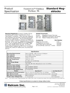
1 1 September 2016 EPS F300 rev 7 Technical data MTL fieldbus networksEaton Electric Limited, Great Marlings, Butterfield, LutonBeds, LU2 8DL, : + 44 (0)1582 723633 Fax: + 44 (0)1582 422283E-mail: 2016 Eaton All Rights ReservedPublication No. EPS F300 rev 7 September 2016 DRAFT 26 June 2015F300 Megablocks are DIN-rail mounted Passive hubs for Foundation fieldbus H1 and Profibus PA networks for general purpose, Zone 2 and division 2 applications. They provide a simple means of connecting field devices to the network trunk cable, and protect the segment from spur short circuits. Megablocks minimize hand wiring and allow individual devices to be added to and removed from the segment without disrupting network communication. A green power LED on each unit indicates whether at least 10V dc is present. F300 Megablocks are available in four, eight, and twelve drop versions. The black Trunk In/Out pluggable connector allows replacement of a megablock without breaking the trunk connection to other devices on the fieldbus segment.
2 The F97 terminator supplied should be mounted in the Trunk-out connection to provide termination when the megablock is located at the end of the fieldbus segment; alternatively, if the segment is extended, it can be removed to ensure the correct termination is connections to the megablock are made using pluggable, grey, screw-terminal or spring clamp terminal connectors. Wire terminations can be made to the individual connectors before plugging them into the megablock . Devices can then be connected and disconnected easily during commissioning. After commissioning, retaining screws are tightened to secure each connector to the megablock . Separate numbered connections are provided for each spur drop. MTL F300 megablock rangePassive hubs for generalpurpose, zone 2 & division 2fieldbus networksSpurGuard is a device-port, short circuit protection technique that minimizes susceptibility to single points of failure.
3 The F300 megablock has built-in SpurGuard protectors that prevent a short circuit in any of the individual field devices or spur cable runs, from bringing down the entire fieldbus segment. A red LED near each spur connection indicates when a spur is shorted and hence in over-current mode. The optional FS32 modules can provide surge protection for the F300 products on both the trunk and spur terminals. These pluggable modules are simple to fit in a new installation, or as a retrofit option. A range of MTL Process Junction Boxes in stainless steel and carbon loaded, glass-reinforced polyester are available for mounting megablock wiring components. They offer plenty of space for termination and wiring, making it easy to install and maintain the fieldbus megablock hazardous area approvals permit installation in a variety of configurations in Zone 2 and division 2 hazardous areas.
4 Typically, F300 Megablocks may be installed with non-sparking (non-arcing) trunk and spur connections. Alternatively, when connected to suitably certified fieldbus power supplies, the trunk may be non-sparking (non-arcing) with non-incendive or intrinsically safe Ex ic spur installed on a non-sparking trunk with Ex ic spurs, an F300-A01 trunk-spur partition must be installed on the F300 megablock . The trunk-spur partition is supplied as a pack of 5, as detailed in the Accessories section of this document. Single-piece Trunk In/Trunk Out connector simplifies installation and maintenance Pluggable trunk and spur surge protection option Choice of rising cage clamp screw or spring clamp terminals Locate megablock in Zone 2 or division 2 Connect to Ex nA, Ex ic or non-incendive devices in Zone 2/ division 2 Connect to Ex d, explosionproof devices in Zone 1/ division 1F300 megablock rangeSeptember 2016 DRAFT 25 June 20152 INSTALLATIONM egablocks can be mounted vertically or horizontally using 35mm DIN rail within a suitable enclosure, such as a field junction box.
5 We have a wide range of standard junction box designs for use with Megablocks. See the data sheet for the range of Process JBs. F300 Megablocks can be clipped onto or removed from the DIN rail without any tools. Use of DIN rail end stops is recommended to prevent sliding in vertical installations. Shown above is an example of a common Fieldbus segment topology. Twelve field devices are connected to a twelve-drop megablock , which is mounted in a field junction box. The trunk connector on the megablock is wired to the segment trunk cable that leads to the control room or marshalling panel where the power supply and second terminator are prevent ground loops, the fieldbus segment shield should only be grounded at one point. This is usually done by grounding the cable shield at the control room end of the PROTECTION - (see right)The design of the F300 has made the installation of effective surge protection on trunk and spur cabling a simple matter, through the use of individual FS32 modules.
6 Grounding bars are available, that clip easily onto the Megablocks to provide both mechanical support for the FS32 modules as well as a way of connecting them to a local low-impedance ground point to dissipate any induced surge currents.++++++SSSSSSSSSSSPWRTRUNKS--+++ ----------+++172839410511612 Partition Required for High Energy Trunk/Ex ic Spurs.!F312 MegablockS-+ requirements35mm DIN railWire to materialPolycarbonateTemperature rangeOperating 45 to +70 CStorage 50 to +85 CVoltage required to activate power dc minimumMinimum input voltageNo. of Ports4 812 input voltagesee certification ratingsMinimum spur output input currentsee certification ratingsTrunk-to-trunk voltage maximumUnloaded current consumption (maximum)No. of Ports4 812 device current 38mA maximum (recommend one device per spur) Spur short-circuit current 56mA maximum Trunk-to-spur voltage drop maximumPHYSICAL NETWORKI EC 6115 8 -2 Foundation fieldbus H1 Profibus PATrunk - F300-BARSpur - F312-BARM4 ground screw positionsGrounding bars on an F312 modules fitted to trunk and two megablock rangeSeptember 2016 DRAFT 25 June 201538-WAY - +-S-+S-+S-+S-+S-+S-+S-+S-+PWR1234567 8F308 MegablockTRUNKP artition Requiredfor High EnergyTrunk/ Ex ic Spurs.
7 ! - +-S-+S-+S-+S-+PWR1234F304 MegablockTRUNKP artition Requiredfor High EnergyTrunk/ Ex ic Spurs.! : Different megablock versions have minor variations in - F312 (showing trunk-spur partition) +S-+S-+S-+S-+S-+S-+S-+S-+S-+S-+S-+PWR123 456789101112F312 MegablockS+ DIMENSIONSThe given data is only intended as a product description and should not be regarded as a legal warranty of properties or guarantee. In the interest of further technical developments, we reserve the right to make design megablock rangeSeptember 2016 Eaton Electric Limited, Great Marlings, Butterfield, LutonBeds, LU2 8DL, : + 44 (0)1582 723633 Fax: + 44 (0)1582 422283E-mail: 2016 Eaton All Rights ReservedPublication No. EPS F300 rev 7 190916 September 2016 EUROPE (EMEA): +44 (0)1582 723633 AMERICAS: +1 800 835 7075 +65 6 645 9888 26 June 20154 APPROVALS - for full certification information visit (Category 3)IECExStandardEN 60079-0 : 2012 EN 60079-11 : 2012 EN 60079-15 : 2010EN 60079-0 : 2012 EN 60079-11 : 2012EN 60079-27 : 2008 IEC60079-0 : 2007-10 IEC 60079-0 : 2011 IEC 60079-11 : 2011 IEC 60079-15 : 2010 IEC60079-0 : 2007-10 IEC 60079-0 : 2011 IEC 60079-11.
8 2011 Approved forE II 3 G Ex nA [ic] IIC T4*Ta = -40 C to +70 CE II 3 G Ex ic IIC T4 Ta = -40 C to +70 CEx nA [ic] IIC T4 Gc* Ta = -40 C to +70 CEx ic IIC T4 Gc Ta = -50 C to +70 C Certificate FMG FMG parameters (Trunk)Non-arcingUi = 24V (IIC)Ui = 32V (IIB, IIA)Ii = 2A Ci = 0, Li = 0 Energy LimitedFISCO icNon-arcingUi = 24V (IIC)Ui = 32V (IIB, IIA)Ii = 2A Ci = 0, Li = 0 Energy LimitedFISCO icCable parameters (Spur)Energy limited Uo = Uo of power supply with voltage limiting to EN 60079-11Io = 56mA, Co = 80nF Lo = (IIC) Lo = (IIB, IIA)Energy LimitedFISCO icEnergy limited Uo = Uo of power supply with voltage limiting to IEC 60079-11Io = 56mA, Co = 80nF Lo = (IIC) Lo = (IIB, IIA)Energy LimitedFISCO ic* An F300-A01 trunk spur partition must be installed for Ex nA [ic] applications. See Accessories below. CountryUSAC anadaAuthorityFMFMFMcFMcStandard3600 2011 3611 2004 3810 2005 ANSI/ISA 60079-0 2009 ANSI/ISA 60079-15 20093600 2011 3611 2004 3810 2005 ANSI/ISA 60079-0 2009 ANSI/ISA 60079-15 2009 CSA No.
9 213-M1987 : 2013 CSA E60079-0: 2002 CSA E60079-15: 2002 CSA No. : 2004 CSA No. 213-M1987 : 2013 CSA E60079-0: 2002 CSA E60079-15: 2002 CSA No. : 2004 Approved forNI/I/2/ABCD/T4 Ta= -50 C to +70 C I /2/IIC/T4 Ta= -50 C to +70 CNI/I/2/ABCD/T4 Ta= -50 C to +70 C I/2/IIC/T4 Ta= -50 C to +70 CNI/I/2/ABCD/T4 Ta= -50 C to +70 C I/2/Ex nA [nL] IIC T4 Ta= -50 C to +70 CNI/I/2/ABCD/T4 Ta= -50 C to +70 C Ex nA IIC T4 Ta= -50 C to +70 CCertificate parameters (Trunk)Non-arcingNon-arcingVmax = 24V Gas Groups A, B (IIC)Vmax = 32V Gas Groups C, D (IIB, IIA)Imax = 2 AVoc = Vmax power supplyNon-arcingVmax = 24V Gas Groups A, B (IIC)Vmax = 32V Gas Groups C, D (IIB, IIA)Imax = 2 AVoc = Vmax power supplyNon-arcingCable parameters (Spur)Non-arcing Non-incendive field wiring Isc = 56mACa = 80nF La = Gas Groups A, B (IIC) La = Gas Groups C, D (IIB, IIA) Po = Groups D, B Po = Groups C, DEnergy limited Isc = 56mACa = 80nF La = Gas Groups A, B (IIC) La = Gas Groups C, D (IIB, IIA)
10 Non-arcingORDERING INFORMATIONF304 4 way megablock screw terminals - including F97 terminatorF308 8 way megablock screw terminals - including F97 terminatorF312 12 way megablock screw terminals - including F97 terminatorF304-PC 4 way megablock spring-clamp terminals - including F97 terminatorF308-PC 8 way megablock spring-clamp terminals - including F97 terminatorF312 -PC12 way megablock spring-clamp terminals - including F97 terminatorF* See datasheet on our web site for full technical specificationACCESSORIESF300-A01-5 Trunk-spur partition pack of 5 FS32*Fieldbus Surge ProtectorF300-BAR-5 Pack of 5 F300 trunk bars304 -BAR-10 Pack of 10 F304 spur bars (two F304-BARs required for each F304)F308 -BAR-10 Pack of 10 F308 spur bars (two F308-BARs required for each F308)F312-BAR-10 Pack of 10 F312 spur bars (two F312-BARs required for each F312)