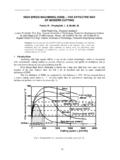
Transcription of PC457L0NIP0F Series PC457L0NIP0F High Speed …
1 PC457L0 NIP0 FSeries1. Recognized by UL1577 (Double protection isolation), file No. E64380 (as model No. PC457L)2. Approved by VDE, DIN EN60747-5-2( ) (as an op-tion), file No. 40009162 (as model No. PC457L)3. Package resin : UL flammability grade (94V-0)( )DIN EN60747-5-2 : successor standard of DIN VDE0884 Features Agency approvals/ComplianceHigh Speed 1Mb/s, high CMR Mini-flat Package OPIC Photocoupler1. Mini-flat 5 pin package2. Double transfer mold package (Ideal for Flow Soldering)3. high Speed response (tPHL : TYP. s, tPLH : TYP. s) 4. high noise immunity due to high instantaneous com-mon mode rejection voltage (CMH : MIN. 15kV/ s, CML : MIN. 15kV/ s)5. high isolation voltage between input and output (Viso(rms) : kV)6. RoHS directive compliant DescriptionPC457L0 NIP0F Series contains a LED optically cou-pled to an OPIC is packaged in a 5 pin isolation voltage(rms) is Speed response (TYP.)
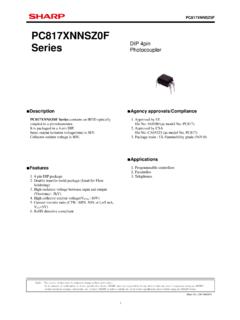
2 1Mb/s) and CMR is MIN. 15 kV/ No.: D2-A05102 FENDate Jun. 30. 2005 SHARP CorporationNotice The content of data sheet is subject to change without prior the absence of confirmation by device specification sheets, SHARP takes no responsibility for any defects that may occur in equipment using any SHARP devices shown in catalogs, data books, etc. Contact SHARP in order to obtain the latest device specification sheets before using any SHARP Series "OPIC"(Optical IC) is a trademark of the SHARP Corporation. An OPIC consists of a light-detecting element and a signal-processing circuit integrated onto a single Programmable controller2. Inverter Applications Internal Connection Diagram2 Sheet No.: D2-A05102 FEN Outline Dimensions(Unit : mm)1. Mini-flat Package [ex. PC457L0 NIP0F]2. Mini-flat Package (VDE option) [ex.]
3 PC457L0 YIP0F]Plating material : SnCu (Cu : TYP. 2%)Product mass : approx. mass : approx. + + resin45 6 codeFactory identification markAnodemarkSHARP mark"S" + + resin45 6 codeFactory identification markPC457 LAnodemark4 VDE Identification markSHARP mark"S"AnodeCathodeGNDVO (Open collector)VCC1345616543 Date code (2 digit) 2nd digitMonth of production1st digitYear of production3repeats in a 20 year cycleSheet No.: D2-A05102 FENPC457L0 NIP0F SeriesFactory identification markFactory identification Markno markCountry of originJapanIndonesiaChina* This factory marking is for identification purpose contact the local SHARP sales representative to seethe actual status of the markThere is no rank mark No.: D2-A05102 FEN Absolute Maximum Ratings4 Electro-optical Characteristics*7PC457L0 NIP0F Series *1 When ambient temperature goes above 70 C, the power dissipation goes down at C.
4 ( )*2 When ambient temperature goes above 70 C, the power dissipation goes down at C. ( )*3 When ambient temperature goes above 70 C, the power dissipation goes down at C. ( )*4 40 to 60%RH, AC for 1minute, f=60Hz*5 For 10sParameterSymbolRatingUnitForward currentIF25mAmAReverse voltageInputOutputVR5 VVPower dissipationP45 Output currentSupply voltageOutput voltagePower dissipationTotal power dissipation1008mW100mWmWVOPOIOVVCCViso (rms)PtotkVOperating temperatureTopr 55 to +125 55 to +85 to +30 to +20 C CStorage temperatureIsolation voltageTstg*4*3*3*2*1*5 Soldering C(Ta=25 C)ParameterSymbolUnitInputForward voltageVFVR everse currentIR ATerminal capacitanceCtV=0, f=1 MHzIF=0, VCC= , VO= (1) A AHigh level supply current (1)ICCH (1) high level supply current (2)ICCH (2)nATransfercharac-teristicstPLH stPHL sCurrent transfer ratio (1)IF=0, VCC=5V, VCM= (p-p), RL= IF=16mA, VCC=5V, VCM= (p-p), RL= kV/ sInstantaneous common mode rejection voltage ( high level output)
5 Instantaneous common mode rejection voltage (Low level output)CMLkV/ sIF=16mAVR=5 VIF=0, VCC=15V, VO=OPENIF=16mA, VCC=5 VRL= MIN. 15 "Low high " propagation delay time" high Low" propagation delay timeCMHI solation resistanceCTR (1)Floating capacitanceCTR (2)IF=16mA, VCC= , VO= , RL= *6 Ta=0 to 70 C*7 It shall connect a by-pass capacitor of F or more between VCC (pin 6 ) and GND (pin 4 ) near the device, when it measures transfer characteristics and the output side transfer ratio (2)*6*6*6 TYP. 60 5003 A A 5 1010 DC500V, 40 to 60%RH1011 CfV=0, f=1 MHzpF 30(Ta=25 C) high level output current (1)IF=0, VCC=15V, VO=15 VIOH (2) high level output current (2)IOH (3) high level output current (3)VOLV ALow level supply currentICCL IF=16mA, VCC= , IO= , VCC=15V, VO=OPEN 120 Low level output voltageResponse timeSheet No.
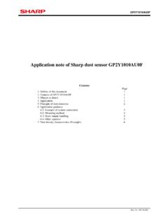
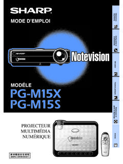
6 : D2-A05102 FEN Model Line-up5 Please contact a local SHARP sales representative to inquire about production SeriesPC457L0 NIP0F PC457L0 YIP0F ApprovedPackageModel EN60747-5-2 Taping3 000pcs/reelSheet No.: Test Circuit for Propagation Delay Test Circuit for Instantaneous Common Mode Rejection VoltagePC457L0 NIP0F inputPulse width10 sDuty ratio1/10 IFMonitorVOVOVCC100 *CL includes the probeand wiring FVOLVOVOVOVCCIFGNDVCM+ (IF=0)(IF=16mA)When SW is AWhen SW is B*CL includes the probe and wiring Forward Current vs. Ambient Power Dissipation vs. Ambient TemperatureForward current IF (mA)Ambient temperature Ta ( C)0510152025 5502550100125758570 Power dissipation P, PO (mW)Ambient temperature Ta ( C)02040456080100 5502550100125 PPO758570 Sheet No.: Output Current vs. Output Relative Current transfer Ratio Forward Current vs.
7 Forward Relative Current transfer Ratio CurrentPC457L0 NIP0F SeriesForward voltage VF (V)Forward current IF (mA) CTa=50 CTa=25 CTa=0 CTa= 25 CTa= 55 CForward current IF (mA)Relative current transfer ratio (%) C50 CTR=100% at IF=16mAOutput current IO (mA)810121416180 Dotted line showspulse characteristics46IF=25mAIF=20mAIF=15mAIF =10mAIF=5mAOutput voltage VO (V)02468101220141618Ta=25 CVCC=5V2 Relative current transfer ratio (%)901001101201301401505060 Ambient temperature Ta ( C) 55 40 20020406010080IF=16mAVCC= at Ta=25 high Level Output Current TemperatureRemarks : Please be aware that all data in the graph are just for reference and not for Propagation Delay Time TemperatureAmbient temperature Ta ( C) high level output current IOH (nA) 2502550751001101001 55 40 20020406010080 Propagation delay time tPHL, tPLH (ns)0800400600 Ambient temperature Ta ( C)tPLHtPHL200IF=16mAVCC=5 VRL= Sheet No.
8 : D2-A05102 FEN8 Design ConsiderationsTransistor of detector side in bipolar configuration may be damaged by static electricity due to its minute handling these devices, general countermeasure against static electricity should be taken to avoid breakdown of devices or degradation of characteristics. Notes about static electricityIn order to stabilize power supply line, we should certainly recommend to connect a by-pass capacitor of F or more between VCC and GND near the case that some sudden big noise caused by voltage variation is provided between primary and secondary terminals of photocoupler some current caused by it is floating capacitance may be generated and result in false operation since current may go through LED or current may change. If the photocoupler may be used under the circumstances where noise will be generated we recommend to use the bypass capacitors at the both ends of detector which is used in this device, has parasitic diode between each pins and are cases that miss operation or destruction possibly may be occurred if electric potential of any pin becomes below GND level even for it shall be recommended to design the circuit that electric potential of any pin does not become below GND product is not designed against irradiation and incorporates non-coherent LED.
9 Design guide DegradationIn general, the emission of the LED used in photocouplers will degrade over the case of long term operation, please take the general LED degradation (50% degradation over 5 years) into the design SeriesParameterInput currentSupply voltageFan out (TTL load) 5 5 UnitmAV SymbolIFVCCNO perating temperature+707 0 CTopr Recommended Foot Print (reference)(Unit : mm) Recommended operating conditions For additional design assistance, please review our corresponding Optoelectronic Application No.: D2-A05102 FEN Manufacturing GuidelinesReflow Soldering:Reflow soldering should follow the temperature profile shown should not exceed the curve of temperature profile and don't solder more than twice. Soldering MethodFlow Soldering :Due to SHARP's double transfer mold construction submersion in flow solder bath is allowed under the below listed soldering should be completed below 260 C and within is within the bounds of 100 to 150 C and 30 to don't solder more than solderingHand soldering should be completed within 3s when the point of solder iron is below 400 don't solder more than noticesPlease test the soldering method in actual condition and make sure the soldering works fine, since the impact on the junction between the device and PCB varies depending on the tooling and soldering ( C)Terminal : 260 C peak( package surface : 250 C peak)Preheat150 to 180 C, 120s or lessReflow220 C or more, 60s or less(min)PC457L0 NIP0F SeriesSheet No.
10 : D2-A05102 FENS olvent cleaning:Solvent temperature should be 45 C or below Immersion time should be 3 minutes or lessUltrasonic cleaning:The impact on the device varies depending on the size of the cleaning bath, ultrasonic output, cleaning time, size of PCB and mounting method of the , please make sure the device withstands the ultrasonic cleaning in actual conditions in advance of mass solvent materials:Ethyl alcohol, Methyl alcohol and Isopropyl alcoholIn case the other type of solvent materials are intended to be used, please make sure they work fine in ac-tual using conditions since some materials may erode the packaging resin. Cleaning instructionsThis product shall not contain the following they are not used in the production process for this substances : CFCs, Halon, Carbon tetrachloride, (Methylchloroform)Specific brominated flame retardants such as the PBBOs and PBBs are not used in this product at product shall not contain the following materials banned in the RoHS Directive (2002/95/EC).