Transcription of PCF8591 8-bit A/D and D/A converter - NXP
1 1. General descriptionThe PCF8591 is a single-chip, single-supply low-power 8-bit CMOS data acquisition device with four analog inputs, one analog output and a serial I2C-bus interface. Three address pins A0, A1 and A2 are used for programming the hardware address, allowing the use of up to eight devices connected to the I2C-bus without additional hardware. Address, control and data to and from the device are transferred serially via the two-line bidirectional functions of the device include analog input multiplexing, on-chip track and hold function, 8-bit analog -to- digital conversion and an 8-bit digital -to- analog conversion. The maximum conversion rate is given by the maximum speed of the Features and benefits Single power supply Operating supply voltage V to V Low standby current Serial input and output via I2C-bus I2C address selection by 3 hardware address pins Max sampling rate given by I2C-bus speed 4 analog inputs configurable as single ended or differential inputs Auto-incremented channel selection analog voltage range from VSS to VDD On-chip track and hold circuit 8-bit successive approximation A/D conversion Multiplying DAC with one analog Applications Supply monitoring Reference setting analog control loopsPCF85918-bit A/D and D/A converterRev.
2 7 27 June 2013 Product data sheetPCF8591 All information provided in this document is subject to legal disclaimers. NXP 2013. All rights data sheetRev. 7 27 June 2013 2 of 31 NXP SemiconductorsPCF85918-bit A/D and D/A converter4. Ordering information Ordering options 5. Marking Table informationType numberPackageNameDescriptionVersionPCF85 91 PDIP16plastic dual in-line package; 16 leads (300 mil)SOT38-4 PCF8591 TSO16plastic small outline package; 16 leads; body width mmSOT162-1 Table optionsProduct type numberSales item (12NC)Orderable part numberIC revisionDelivery formPCF8591P933768130112 PCF8591P,1121tubePCF8591T/2935276541512 PCF8591T/2,5121tube, dry pack935276541518 PCF8591T/2,5181tape and reel, dry pack, 13 inch Table codesType numberMarking codePCF8591 PPCF8591 PPCF8591 TPCF8591 TPCF8591 All information provided in this document is subject to legal disclaimers. NXP 2013. All rights data sheetRev. 7 27 June 2013 3 of 31 NXP SemiconductorsPCF85918-bit A/D and D/A converter6.
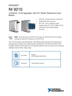
3 Block diagram 7. Pinning Pinning Fig diagram of PCF8591mbl821I2C BUSINTERFACEANALOGUEMULTIPLEXERPOWER ONRESETOSCILLATORSAMPLEANDHOLDSAMPLEANDH OLDCONTROLLOGICDAC DATAREGISTERSUCCESSIVEAPPROXIMATIONREGIS TER/LOGICDACSTATUSREGISTERPCF8591 ADC DATAREGISTERSCLSDAA0A1A2 EXTAIN0 AIN1 AIN2 AIN3 AOUTVREFAGNDOSCVSSVDDCOMPARATORTop view. For mechanical details, see Figure 22 on page view. For mechanical details, see Figure 23 on page configuration for PCF8591P (DIP16)Fig configuration for PCF8591T (SO16)3&) 3 $,1 9'' $,1 $287 $,1 95() $,1 $*1' $ (;7 $ 26& $ 6&/ 966 6'$DDD 3&) 7 $,1 9'' $,1 $287 $,1 95() $,1 $*1' $ (;7 $ 26& $ 6&/ 966 6'$DDD PCF8591 All information provided in this document is subject to legal disclaimers. NXP 2013. All rights data sheetRev. 7 27 June 2013 4 of 31 NXP SemiconductorsPCF85918-bit A/D and D/A Pin description Table descriptionSymbolPinDescriptionAIN01anal og inputs (A/D converter )AIN12 AIN23 AIN34A05hardware slave addressA16A27 VSS8ground supply voltageSDA9I2C-bus serial data input and outputSCL10I2C-bus serial clock inputOSC11oscillator input/outputEXT12external/internal switch for oscillator inputAGND13analog ground supplyVREF14voltage reference inputAOUT15analog output (D/A converter )VDD16supply voltagePCF8591 All information provided in this document is subject to legal disclaimers.
4 NXP 2013. All rights data sheetRev. 7 27 June 2013 5 of 31 NXP SemiconductorsPCF85918-bit A/D and D/A converter8. Functional AddressingEach PCF8591 device in an I2C-bus system is activated by sending a valid address to the device. The address consists of a fixed part and a programmable part. The programmable part must be set according to the address pins A0, A1 and A2. The address is always sent as the first byte after the start condition in the I2C-bus protocol. The last bit of the address byte is the read/write-bit which sets the direction of the following data transfer (see Ta b l e 5 on page 13, Figure 15 on page 13 and Figure 16 on page 13). Control byteThe second byte sent to a PCF8591 device is stored in its control register and is required to control the device function. The upper nibble of the control register is used for enabling the analog output, and for programming the analog inputs as single-ended or differential inputs. The lower nibble selects one of the analog input channels defined by the upper nibble (see Figure 4).
5 If the auto-increment flag is set, the channel number is incremented automatically after each A/D the auto-increment mode is desired in applications where the internal oscillator is used, the analog output enable flag must be set in the control byte (bit 6). This allows the internal oscillator to run continuously, by this means preventing conversion errors resulting from oscillator start-up delay. The analog output enable flag can be reset at other times to reduce quiescent power selection of a non-existing input channel results in the highest available channel number being allocated. Therefore, if the auto-increment flag is set, the next selected channel is always channel 0. The most significant bits of both nibbles are reserved for possible future functions and must be set to logic 0. After a Power-On Reset (POR) condition, all bits of the control register are reset to logic 0. The D/A converter and the oscillator are disabled for power saving. The analog output is switched to a high-impedance information provided in this document is subject to legal disclaimers.
6 NXP 2013. All rights data sheetRev. 7 27 June 2013 6 of 31 NXP SemiconductorsPCF85918-bit A/D and D/A converter D/A conversionThe third byte sent to a PCF8591 device is stored in the DAC data register and is converted to the corresponding analog voltage using the on-chip D/A converter . This D/A converter consists of a resistor divider chain connected to the external reference voltage with 256 taps and selection switches. The tap-decoder switches one of these taps to the DAC output line (see Figure 5).The analog output voltage is buffered by an auto-zeroed unity gain amplifier. Setting the analog output enable flag of the control register switches this buffer amp on or off. In the active state, the output voltage is held until a further data byte is on-chip D/A converter is also used for successive approximation A/D conversion. In order to release the DAC for an A/D conversion cycle the unity gain amplifier is equipped with a track and hold circuit. This circuit holds the output voltage while executing the A/D byteDDD 06%/6%&21752/ %<7($872 ,1&5(0(17 )/$* DFWLYH LI $1$/2* 287387 (1$%/( )/$* DQDORJ RXWSXW DFWLYH LI $1$/2* ,1387 352*5$00,1* IRXU VLQJOH HQGHG LQSXWV $,1 FKDQQHO $,1 FKDQQHO $,1 FKDQQHO $,1 FKDQQHO WKUHH GLIIHUHQWLDO LQSXWV$,1 $,1 $,1 FKDQQHO VLQJOH HQGHG DQG GLIIHUHQWLDO PL[HG $,1 FKDQQHO $,1 FKDQQHO WZR GLIIHUHQWLDO LQSXWVFKDQQHO FKDQQHO $,1 $ ' &+$11(/ 180%(5 FKDQQHO FKDQQHO FKDQQHO FKDQQHO ;;; ;;;$,1 FKDQQHO $,1 $,1 FKDQQHO $,1 $,1 FKDQQHO $,1 PCF8591 All information provided in this document is subject to legal disclaimers.)))))]
7 NXP 2013. All rights data sheetRev. 7 27 June 2013 7 of 31 NXP SemiconductorsPCF85918-bit A/D and D/A converterThe formula for the output voltage supplied to the analog output AOUT is shown in Figure 6. The waveforms of a D/A conversion sequence are shown in Figure 7. Fig resistor divider chainFig data and DC conversion characteristicsDDD 5 $*1'95()' ' ' 7$3'(&2'(5 5 5 5 5 ))'$& RXWDDD 06%/6%' ' ' ' ' ' ' ' '$& GDWDUHJLVWHU9$287 9$*1' 'L L L 995() 9$*1' 9669$*1'995() )( ))'$& KH[ 9''9$287 PCF8591 All information provided in this document is subject to legal disclaimers. NXP 2013. All rights data sheetRev. 7 27 June 2013 8 of 31 NXP SemiconductorsPCF85918-bit A/D and D/A converter A/D conversionThe A/D converter uses the successive approximation conversion technique. The on-chip D/A converter and a high-gain comparator are used temporarily during an A/D conversion A/D conversion cycle is always started after sending a valid read mode address to a PCF8591 device.]
8 The A/D conversion cycle is triggered at the trailing edge of the acknowledge clock pulse and is executed while transmitting the result of the previous conversion (see Figure 8). Once a conversion cycle is triggered, an input voltage sample of the selected channel is stored on the chip and is converted to the corresponding 8-bit binary code. Samples picked up from differential inputs are converted to an 8-bit two's complement code (see Figure 9 and Figure 10). Fig conversion sequenceDDD WLPHKLJK LPSHGDQFH VWDWH RISUHYLRXV YDOXH KHOG LQ '$& UHJLVWHUSUHYLRXV YDOXH KHOGLQ '$& UHJLVWHUYDOXH RI GDWD E\WH 6 $$&21752/ %<7($'$7$ %<7( $'$7$ %<7( $''5(66 SURWRFRO6&/6'$9$287 Fig conversion sequenceS1 AAAAADDRESSDATA BYTE 1 DATA BYTE 2 DATA BYTE 0129819191protocolSCLSDA conversion of byte 2conversion of byte 3conversion of byte 1transmissionof previouslyconverted bytesampling byte 2sampling byte 3sampling byte 1transmissionof byte 1transmissionof byte 2mbl829 PCF8591 All information provided in this document is subject to legal disclaimers.))))
9 NXP 2013. All rights data sheetRev. 7 27 June 2013 9 of 31 NXP SemiconductorsPCF85918-bit A/D and D/A converterThe conversion result is stored in the ADC data register and awaits transmission. If the auto-increment flag is set, the next channel is first byte transmitted in a read cycle contains the conversion result code of the previous read cycle. After a POR condition, the first byte read is 80h. The protocol of an I2C-bus read cycle is shown in Section maximum A/D conversion rate is given by the actual speed of the I2C-bus. Fig conversion characteristics of single ended inputs100001020304234254255 VAIN VAGNDVlsbFEFFHEX codeVREF VAGND256 Vlsb =mbl830 PCF8591 All information provided in this document is subject to legal disclaimers. NXP 2013. All rights data sheetRev. 7 27 June 2013 10 of 31 NXP SemiconductorsPCF85918-bit A/D and D/A converter Reference voltageFor the D/A and A/D conversion, either a stable external voltage reference or the supply voltage must be applied to the resistor divider chain (pins VREF and AGND).
10 The AGND pin has to be connected to the system analog ground. It may have a DC off-set with reference to low frequency can be applied to the VREF and AGND pins. This allows the use of the D/A converter as a one-quadrant multiplier (see Section 10 and Figure 6)The A/D converter can also be used as a one or two quadrant analog divider. The analog input voltage is divided by the reference voltage. The result is converted to a binary code. In this application, the reference voltage must be kept stable during the conversion OscillatorAn on-chip oscillator generates the clock signal required for the A/D conversion cycle and for refreshing the auto-zeroed buffer amplifier. When using this oscillator the EXT pin must be connected to VSS. The oscillator frequency is available at the OSC the EXT pin is connected to VDD, the oscillator output OSC is switched to a high-impedance state allowing to feed an external clock signal to 10. A/D conversion characteristics of differential inputs102 2 HEXCODE 127 128 11261277F7E0201 FFFE818000 VREF VAGND256 Vlsb =VAIN + VAIN Vlsbmbl831 PCF8591 All information provided in this document is subject to legal disclaimers.