Transcription of PCI Express PIPE Overview - MindShare
1 PCI Express pipe Overview MindShare , Inc. Dave Dzatko March 2004. Introduction 4. pipe Architecture ..4. MAC Architecture .6. PHY/MAC Interface ..7. PCS Architecture .. 9. PMA Architecture 12. pipe Functionality and Features ..13. pipe Signal Organization 14. pipe PLL .15. Transmitter Sub-block .16. Receiver Sub-block .16. pipe Signal Descriptions 18. pipe Summary 20. PCI Express pipe . Introduction pipe , which stands for the Physical Interface for PCI Express Specification developed by Intel, has the stated intent of providing a standard interface between the internal logic of a PCI Express design and the analog and high-speed circuitry required to implement the serial link. This purpose of this functional separation is to allow ASIC and integrated circuit designers to focus on the PCI Express device core, Transaction, Data Link and logical Physical Layers, while relying on the pipe -compliant physical design (PHY) for the electrical interface of the design.
2 Other vendors can then provide macrocells to handle this high-speed analog interface layer, resulting in reduced time and risk for the overall design cycle. The pipe spec defines standard functionality that a pipe -compliant PHY needs to implement, as well as a standard parallel interface between the PHY and the internal logic referred to in the spec as the Media Access Layer (MAC). The MAC in turn connects to the PCI Express Data Link Layer logic . The pipe spec builds on the PCI Express base spec, so it should be noted that a working knowledge of that document is essential for a good understanding of the pipe . spec. This paper is based on the version of the pipe spec, and provides a brief introduction only. For more information on pipe , refer to Intel's web site1.
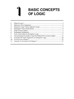
3 For more information on PCI Express , refer to MindShare 's web site2 or the PCI. Special Interest Group site3. pipe Architecture The pipe architecture block diagram is shown in Figure 1. As mentioned earlier, the Data Link Layer (DLL) logic interfaces with the MAC, although the spec doesn't define this interface or any others except the one between the PHY and the MAC. All the other interconnects are understood to be implementation specific. The interface between the MAC and the PCS (Physical Coding Sub- layer) is a dual simplex, parallel bus called the PHY/MAC interface. The PCS and PMA (Physical Media Attachment Layer) interface is not defined by the spec. The functionality of the PCS and PMA are described conceptually in the pipe . and PCI Express specifications but, again, no specific implementations are implied.
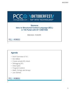
4 The PMA contains the high-speed analog and digital circuitry that connects to the PCI Express link via differential transmitters and receivers. The pipe spec notes that there is overlap between it and the PCI Express spec, and states that in case of any conflict between them, the PCI Express spec takes precedence. 1. 2. 3. 3. PCI Express pipe . MAC PCS PMA. (Media (Physical (Physical Access PHY/ Coding Media RX. TO Layer) MAC Sub-layer) Attachment DLL Layer). TX. pipe SPEC. PCI-E PHY SPEC. Figure 1. pipe Architecture MAC Architecture The MAC contains many of the PCI Express logical Physical Layer circuits (such as the Link Training and Status State Machine (LTSSM), data scrambling, 8b/10b encoding, and byte striping), and functions as the bridge between the DLL and the PHY/MAC interface.
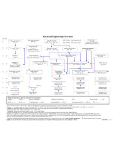
5 MAC PCS. (Media (Physical Access PHY/ Coding Layer) MAC Sub-layer). TO. DLL. Implementation Specific (Not Specified). Figure 2. MAC Architecture 4. PCI Express pipe .. PHY/MAC Interface The PHY/MAC interface is the major normative area of the pipe spec, as shown in Figure 3. The pins that make up the interface and their functionality are described in the spec, and timing diagrams are provided to show the synchronous timing relationships, but no detailed timing parameters for the signals are given. Instead, the spec provides a description of implementation-specific timings that a vendor of a pipe -compliant PHY macrocell or discrete chip must specify. Much of the functionality of the PHY/MAC Interface is described in the spec using timing diagrams, which are not repeated here.
6 MAC TxData (8 or 16) PCS. (Media TxDataK (1 or 2) (Physical Access Coding Layer) Command (7). Sub-layer). RxData (8 or 16). RxDataK (1 or 2). Status (6). PCLK. Figure 3. PHY/MAC Interface The PHY/MAC Interface is a parallel interface for transferring data to be transmitted on the PCI Express bus. The width of this parallel interface for bytes of data is shown as either be 8 or 16 bits in each direction. In addition to the data path, the PHY/MAC Interface includes one Control (K) lines in each direction for each byte to indicate whether the corresponding byte is a data or a control character. If the interface is 16 bits wide, there will be two Control lines, but only one is needed if the interface is 8 bits wide. Seven signals from the MAC to the PCS make up the command bus that allows the MAC to tell the PHY to begin performing a variety of tasks, including: Begin Receiver Detection Enter the External Loop-back state Enter the Electrical Idle state Set the current running disparity to positive or negative Invert the polarity of the received data 5.
7 PCI Express pipe . Reset the PHY. Power down the PHY into various Power Management (PM) states The PHY/MAC Interface also includes a 6-bit status bus for communication of PHY status from the PCS to the MAC. The status bus has codes and signals that indicate conditions including: The PHY has obtained symbol lock The received data is valid The PHY has completed various PM state transitions The PHY has detected that a receiver is attached The PHY has detected an Electrical Idle state on the Link There are 8 additional status and error codes defined The PHY includes a clock output called PCLK which is used to synchronize data transfers across the parallel PHY/MAC Interface. If the parallel interface is 16. bits wide, then PCLK runs at 125 MHz, but if the interface is 8 bits wide, then the PCLK runs at 250 MHz so as to maintain the data rate with respect to the serial link.
8 PCS Architecture The Physical Coding Sub-layer (PCS), although part of the Logical Sub-block of the PHY, is included within a pipe -compliant discrete device or macrocell. The PCS supports the PHY side of the standard PHY/MAC Interface as well as an implementation-specific interface between it and the Physical Media Attachment Layer (PMA). No specifications are provided in the pipe document for this interface. The clock reference input (CLK) is used by the PHY to generate the internal bit rate clocks for transmitting and receiving PCI Express data. Specifications for this implementation-specific clock, which will be used internally to generate the bit- rate clock for the PHY transmitter and receiver as well as the PCLK for the PHY/MAC interface, must be provided by pipe -compliant PHY vendors.
9 Spread spectrum modulation that matches the system reference clock modulation is permitted for this signal. The 8B/10B logic required by PCI Express resides in the PCS. The input to the 8B/10B encoder is the data or control character from the PHY/MAC Interface, the value of the current running disparity, and the TxDataK signal that is needed because the encoding for a data character is different from that of a control character. The PCS also contains the elastic buffer used to compensate for the slight variations in frequency between the transmitter's clock and the clock used by the receiver to process the incoming data. 6. PCI Express pipe . CLK (Implementation Specific). PHY/ PCS. MAC Implementation (Physical Specific Standard Coding Interface Sub-layer) (Not Specified).
10 Figure 4. PCS Architecture After reset, the first state of the link initialization and training process is the receiver detect, during which the transmitter detects whether a receiver is attached to it at the other end of the link. The PCS contains the logic that controls the receiver detection and reports the detect status to the MAC via the PHY/MAC. Interface. The PCS also contains a Phase Lock Loop (PLL) to generate the internal, high speed clocks used for the PHY based on the CLK input. PMA Architecture The Physical Media Attachment (PMA) Layer implements the high-speed analog and digital circuitry for PCI Express signaling, including the differential drivers and receivers for each lane of a link. Although the data is serially transmitted over the link, the connection from the PCS to the PMA is a ten bit wide, implementation-specific parallel interface.