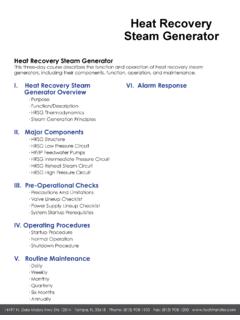
Transcription of Performance Analysis of a Heat Recovery Steam …
1 Performance Analysis of a heat Recovery Steam Generator Ramakrishna Kolluru Y. Dhanasekhar Research Scholar, Asst. Prof. & Department of Mechanical Engineering Head of Department of Mechanical Engineering Kakinada Institute of Technology & Science Kakinada Institute of Technology & Science Diwili, , India Diwili, , India. M. V. H. Satish Kumar Associate Prof Department of Mechanical Engineering PVP Siddhartha Institute of Technology, Kanuru Vijayawada -7, India Abstract : In view of the energy crisis, the heat Recovery system at any stage is very much important is the field of conservation of energy. The heat Recovery Steam Generator is one of the Critical components is the combined cycle (Gas Turbine cycle and Steam Power cycle) and is the most efficient energy conversation system in recent trends.
2 Its function is to recover the waste heat present in the exhaust Gases of the Gas turbine cycle and to generate the Steam to run a Steam power cycle. This is an attempt to provide some information in this direction for the next Generation. This work deals with to study the Performance and Analysis of a Triple pressure heat Recovery Steam generator in combined cycle power plant at different ambient conditions. The results shows that the Increase of ambient temperature Increases the Exhaust outlet temperature from the gas turbine and thus increases the heat content present in the flue gases. so it is possible to generate more amount of Steam at high ambient temperatures. It is observed that the percentage of heat utilization increases because the inlet temperature of heat Recovery Steam Generator increases with increase of ambient temperature.
3 It is noticed that the percentage of heat utilization increases as , 61%, for the ambient temperatures of 150c, 300c, 450c, respectively. Key Words: Combined cycle , Gas Power Cycle, heat Recovery Steam Generator, Steam power cycle, Ambient Temperature , Exhaust gas outlet temperature, Percentage of heat Utilization. Combined Cycle Power Plants are finding wider acceptance because it utilizes the Nature Gas which is available huge amount and it gives higher overall thermal efficiencies. It has Fast Start up capabilities and required least amount of cooling water for its functions. The Optimization of heat Recovery Steam Generator is particularly important for design of combined plants to maximize the work to be developed in the vapour cycle. Multi Pressure Steam generation in heat Recovery Steam generator of combined Power plant improves the Performance of the plant.
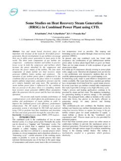
4 The Optimization of the heat Recovery Steam Generator is of particular interest in order to improve the efficiency of the heat Recovery from the Gas turbine exhaust and to maximize the Power production in the Vapour cycle. work : The Present work deals with to study the data collected from the Lanco Power Plant with heat Recovery Steam Genarator. Fig. Layout of Lanco Power Plant with HRSG (Courtesy-LANCO) The Fig. shows the different points and the necessary information of the particular point in order to give the quality of Steam / Gas temperature, Enthalpy and so on. Line Diagram of combined power plant with HRSG. The Fig Shows the Line of Diagram of Combined Cycle Power plant with heat Recovery Steam Generator. The following Tables give the information regarding the operation of plant and values of different points of the combined cycle plant.
5 International Journal of Engineering Research & Technology (IJERT) ISSN: (This work is licensed under a Creative Commons Attribution International License.)Vol. 3 Issue12, December-20145612. DESCRIPTION HEATRECOVERY Steam GENERATOR (HRSG) About the heat Recovery Steam Generator System Description: Each HRSG is of Triple pressure, natural circulation, horizontal type mainly comprising of 1 HP/IP/LP boiler drums 2 Various heat transfer sections 3 Drains and vents heat transfer sections are arranged in the direction of flow of exhaust gasses from the GT. In addition to the above HRSG also comprises, inlet Flue gas duct, outlet flue gas duct, main stack, and auxiliaries such as continuous and intermittent blow-down tanks etc. The drum level to normal value. Attemperator is provided, utilizing feed water, to HP super heater sections and re-heater section.
6 No attemperation Feed water to each drum goes via modulating level control to maintain is required for LP super heater. 3. WORKING OF HRSG The HRSG is designed to extract maximum recoverable heat from the exhaust gas of the gas turbine. For this purpose the exhaust gas flow from the gas turbine is arranged in a direction counter to the water/ Steam circuit of HRSG. The exhaust gas 4. COLLECTED DATA FOR DIFFERENT OPERATING AMBIENT TEMPERATURE CONDITIONS. Table : Area details of each section in HRSG Item description (HRSG) AREA (m2) 1 HP super heater 14754 2 IP super heater 3 LP super heater 4 HP Evaporator 48610 5 IP Evaporator 24499 6 LP Evaporator 7 HP Economizer 8 IP Economizer 9 CPH 10 Reheater From the gas turbine enters the HPSH 3, RH 2, and HPSH 2, RH 1, and HP super heater 1. From the Super heaters, the exhaust gases travel through the HP boiler evaporator ,IPSH ,LPSH , HP Economizer 3 , IP Evaporator , HP economizer 2 modules, IP Economizer, HP Economizer 1 , LP Evaporator and finally through the CPH (Condensate Pre heater) before exhausted to the atmosphere by the stack.
7 Case 1: For 15 c as ambient temperature Table : The table of values for 15 C : Case Description 15 C, 100% GT load Ambient temperature c 15 Relative humidity % 60 GT output KW 261000 Ambient pressure Bar ST output KW 131313 Gross plant output KW 392313 Gross plant efficiency % Gross heat rate KJ/KWh Net power output KW 383470 Net heat rate KJ/KWh cc M (T/hr) P (bar, a) T ( C) h (KJ/Kg) G1 G2 G3 - - G4 F1 F2 F3 - - - - F4 S1 S2 S3 S4 S5 S6 S7 S8 S9 S10 International Journal of Engineering Research & Technology (IJERT) ISSN: (This work is licensed under a Creative Commons Attribution International License.)Vol. 3 Issue12, December-2014562S11 S12 S13 S14 S15 S16 S17 S18 S19 W1 W2 W3 W4 W5 W6 W7 W8 W9 W10 W11 W12 W13 W14 W15 W16 W17 W18 22222m3/hr W19 22222m3/hr Case 2: For 30 c as ambient temperature.
8 The figure shows different points and the necessary information of the perticular point in order to say the quality of the Steam /gas temperature, enthalphy and so on. The following tables gives the information regarding the operation of plant and the values of different points of the Combined cycle plant. Case Description 30 C, 100% GT load Ambient temperature c 30 Relative humidity % 60 GT output KW 241300 Ambient pressure Bar ST output KW 124638 Gross plant output KW 365938 Gross plant efficiency % Gross heat rate KJ/KWh Net power output KW 357292 Net heat rate KJ/KWh Stream M (T/hr) P (bar, a) T ( C) h (KJ/Kg) G1 G2 G3 - - G4 F1 F2 F3 - - - - F4 S1 S2 S3 S4 S5 S6 S7 S8 S9 S10 S11 S12 S13 S14 S15 S16 S17 S18 S19 W1 W2 W3 W4 W5 W6 W7 W8 W9 W10 W11 W12 W13 W14 W15 W16 W17 W18 22222m3/hr W19 22222m3/hr International Journal of Engineering Research & Technology (IJERT) ISSN: (This work is licensed under a Creative Commons Attribution International License.)
9 Vol. 3 Issue12, December-2014563 Case 3: For 45 C as ambient temperature. The figure shows different points and the necessary information of the perticular point in order to say the quality of the Steam /gas temperature, enthalphy and so on. The following tables gives the information regarding the operation of plant and the values of different points of the Combined cycle plant. Table : Table of values for 45 C are: Case Description 45 C, 100% GT load Case Description Ambient temperature C Ambient temperature Relative humidity % Relative humidity GT output KW GT output Ambient pressure Bar Ambient pressure ST output KW ST output Gross plant output KW Gross plant output Gross plant efficiency % Gross plant efficiency Gross heat rate KJ/KWh Gross heat rate Net power output KW Net power output Net heat rate KJ/KWh Net heat rate Table : Table of values for the different points in HRSG Stream M (T/hr) P (bar, a) T ( C) h (KJ/Kg) G1 G2 G3 - - G4 F1 F2 F3 - - - - F4 S1 S2 S3 S4 S5 S6 S7 S8 S9 S10 S11 S12 S13 S14 S15 S16 S17 S18 S19 W1 W2 W3 W4 W5 W6 W7 W8 W9 W10 W11 W12 W13 W14 W15 W16 W17 W18 22222m3/hr W19 22222m3/hr 5.
10 Performance Analysis The Performance of the HRSG equipment is calculated and its parameters are listed below at various points in the HRSG equipment. CALCULATIONS Formulae used in calculation for all ambient temperatures: 1. heat content passed within the HRSG: Q = m cp (tin-tout) 2. heat developed within HP-Super heater: Q = m cp (tin-tout) 3. heat developed within IP-Super heater: Q = m cp (tin-tout) 4. heat developed within LP-Super heater: Q = m cp (tin-tout) 5. heat developed within the HP-Evaporator: Q = m cp (tin-tout) 6. heat developed within the IP-Evaporator: Q = m cp (tin-tout) 7. heat developed within the LP-Evaporator: Q = m cp (tin-tout) 8. heat developed within the HP-Economizer: Q = m cp (tin-tout) 9. heat developed within the IP-Economizer: Q = m cp (tin-tout) 10. heat developed within LP-Economizer: Q = m cp (tin-tout) 11.