Transcription of PERFORMANCE TEST OF A CENTRIFUGAL PUMP
1 75 EXPERIMENT NUMBER 7 PERFORMANCE TEST OF A CENTRIFUGAL PUMP OBJECTIVE The primary objectives of this experiment is to measure the PERFORMANCE of a CENTRIFUGAL pump and compare the results to the manufacturers specifications. Secondary objectives are to familiarize the student with the characteristics of a CENTRIFUGAL pump and to introduce the student to the homologous scaling relationships. In addition, this experiment gives the student further exposure to the use of computerized data acquisition systems. Additional objectives may be specified by the instructor. REFERENCES Munson, B. et al: Fundamentals of Fluid Mechanics, Wiley Potter, M. and Wiggert, D.: Mechanics of Fluids, Prentice Hall White, F.: Fluid Mechanics, McGraw-Hill INTRODUCTION The most common machine for causing liquids to flow through piping systems is the CENTRIFUGAL pump. The CENTRIFUGAL pump is well suited to situations requiring moderate to high flowrates and modest increases in head (or pressure).
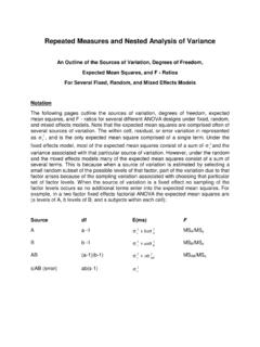
2 Typical applications include municipal water supply systems, circulating water heating and cooling system for buildings, pumps in dishwashers and clothes washing machines and the cooling water circulating pump in an automobile engine. For very high pressure, low flow applications, positive displacement pumps are more suitable. Positive displacement pumps move fluids with pistons, gears or vanes and flowrate is a function of rotational speed and has little if any dependence on the pressure rise. A common application of a positive displacement pump is that used to supply high pressure oil for hydraulic actuators such as those on a large earth moving machines. 76 A sketch of a typical CENTRIFUGAL pump is shown in Figure Fluid which flows into the impeller at the inner radius is given significant angular momentum and kinetic energy as it flows radially outward. After the fluid leaves the outer radius of the impeller, it is diffused or slowed down resulting in a significant increase in pressure.
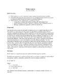
3 The actual head rise (H) produced by a CENTRIFUGAL pump is a function of the flowrate (Q). It is possible to determine the head-flow relationship by appropriate selection of the geometry of the impeller blades. Normally, pumps are designed so that the head decreases with increasing flow since such a design results in a stable flowrate when the pump is connected to a piping system. A typical head flow curve for a pump is shown in Figure If the mechanical energy equation is applied between two points in a piping system on opposite sides of the pump, the result is: HVgPzVgPzhPl++++++++++++====++++++++++++ 1211222222 Hp is the pump head, and hl is the total head loss in the associated piping. If section 1 is located at the pump inlet and section 2 at the pump outlet, the hl term in the mechanical energy equation is zero. If there is include piping, either upstream or downstream, the hl term may be greater than zero. For a given pump operating at a given rotational speed, there is only one operating point where the the geometry of the impeller blades is optimum.
4 This fact, combined with other losses results in an efficiency which is a function of the flowrate. The efficiency is defined as the ratio of the fluid work to the shaft power input to the pump: ====QHPpshaft The PERFORMANCE of CENTRIFUGAL pumps is only partially determined by analysis - testing is usually required. The PERFORMANCE of a pump is dependent on the impeller and casing geometry, the size of the pump, the rotational speed and the properties of the flowing fluid. Fortunately, it is not necessary to vary all of these parameters in order to determine the PERFORMANCE of pumps. Two geometrically similar pumps which have flowrates adjusted so that the ratio of tangential to radial fluid velocities are the same are said to be homologous. More specifically, two pumps are said to be homologous if they are geometrically similar and the following two dimensionless parameters are the same: Figure - Cutaway sketch of typical CENTRIFUGAL pump.
5 From Munson et al, Fundamentals of Fluid Mechanics Figure - Typical PERFORMANCE curves for CENTRIFUGAL pump. From Munson et al. Fundamentals of Fluid Mechanics. 77 1322 2========QNDgHND N is the angular speed and D is the diameter. The diameter is a measure of the length scale of the pump. A larger diameter implies that all the other dimensions of the pump are proportionally larger. The diameter used is usually the outer diameter of the impeller. With these relationships, it is possible to estimate the PERFORMANCE of one pump with one diameter by testing another pump with a different diameter. It is also possible to determine the effect of a change in angular speed. If a pump is tested at for example at 1800 rpm, then it is possible to estimate the PERFORMANCE at 3600 rpm. The scaling permitted by the homologous pump relationships isn't perfect. For example, the absolute roughness height of the casing may be a function of the manufacturing process and so the relative roughness might be a function of scale.
6 This problem, together with other loss effects means that errors of a few percent may result from the application of the homologous machine relationships. THE EXPERIMENTAL APPARATUS The apparatus consists of a pump, motor, flow control valve, shaft torque meter, pressure transducers at the inlet and the outlet and two inline paddle wheel flowmeters as shown in Figure Only one of the flowmeters is shown in Figure This is a 2" unit which measures all the flow that goes through the pump. Unfortunately, this flowmeter is unreliable at flowrates of less than about 15 gpm. Fluid velocity in the pipe is insufficient to overcome friction in the paddle wheel. However, there is a smaller, 3/4" flowmeter in the system which can be used at lower flows. This unit is shown in the system schematic for the Pipe Friction Experiment, Experiment 3. It only measures the Figure - Sketch of pump test apparatus 78 flowrate through the three smallest pipes used for that experiment.
7 To make use of it, the valves in the test rig must be set so that all of the pump flow goes through these smaller pipes. This small flowmeter can then be used at low pump flowrates. This flowmeter is not valid at flows greater than 20 gpm. The pump is a Price Pump Co. Model B-15, size 1-1/2x2x6. The size information indicates a 1-1/2 inch outlet pipe and a 2 inch inlet pipe with a nominal maximum impeller diameter of 6 inches. Our pump has a inch impeller. Manufacturer's data for this pump is contained in Figures and The motor is a two speed type that can operate at either a nominal 1800 or 3600 rpm depending on the setting of the connected control. The pressure transducers and the two flowmeters are connected to an IBM PC controlled data acquisition system. Each of the devices which are connected to the DAS has a voltage output which is proportional to the magnitude of the measured variable. See the above information on the validity of the flowmeter data.
8 The shaft torque meter is a shaft which twists in torsion in linear proportion to the applied torque. This twist is measured by a scale on the rotating device. The torquemeter can be read using a strobotachometer flashing at the shaft rotational speed. The strobotach can also be used to measure the shaft rotational speed. Both the inlet and outlet pressure taps are located on two inch schedule 40 plastic pipe which has an inside diameter of inches. The actual outlet diameter of the pump is inches and there is a sudden expansion to inches and then short section of pipe before the outlet pressure tap. You may want to evaluate these sources of head loss when using the mechanical energy equation to evaluate the pump head. A bourdon type pressure gage is also connected to the outlet pressure tap. This gage can be used to check the accuracy of the outlet pressure transducer. The accuracy of the inlet pressure transducer can be checked by applying the Bernoulli equation between the water surface in the supply tank and the location of the inlet pressure tap.
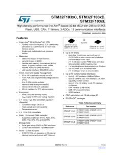
9 Since the pressure and velocity at the water surface are both zero, the Bernoulli equation takes the form: zPVgtt11122====++++ where z1 is the elevation of the water surface relative to the inlet pressure tap and Pt1 and Vt1 are the pressure and velocity in the pipe at the inlet pressure tap. Part of the same flow system is a tank placed on a mechanical scale as shown in Figure 1 of the pipe friction experiment. Using appropriate valves, the flow can be diverted to this weigh tank. Together with a timer, this system can be used to calibrate the 2" paddle wheel flow meter. 79 Figure - Head vs. flow for Price Pump Model B15, 1 1/2x2x6, at 3600 and 1800 rpm. Manufacturers data sheet. 0 10 20 30 40 50 60 70 0 20 40 60 80 100 120 140 160 180 200 US GALLONS PER MINUTEP rice PumpModel " Impeller rpm3600 rpm % Figure - Efficiency vs. flow for Price Pump model B15, 1 1/2x2x6, with " dia. impeller for 1800 and 3600 rpm.
10 Based on mfg. data. 80 REQUIRED TEST DATA The electrical output of the pressure transducers and the flowmeter might drift in time. Furthermore, the output of the electrical devices might be affected by loose connections. As a result, it is desirable to perform some initial calibration runs to check out these devices. Turn on the data acquisition system. At the C> prompt, type CD\DAS and then ACQUIRE. At the prompt for a configuration file, type Enter a group name at the prompt and enter 0 for the sampling rate. The data acquisition system is now set up to take the calibration data. Take a first run (with the pump still not running). The program will prompt for the readings of the bourdon gage, the water weight and the time to collect the water. Read the bourdon gages and type in the value. For this run, the amount of water collected is zero and type in any non- zero time. Take another run with these same conditions. The remaining calibration runs are taken with the pump running.