Transcription of PERFORMER SERIES THUNDER SERIES AVS …
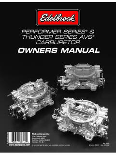
1 PERFORMER SERIES &. THUNDER SERIES AVS . CARBURETOR. OWNERS MANUAL. 2005 edelbrock Corp. edelbrock Corporation 2700 California Street Torrance, CA 90503. Tech Line: 1-800-416-8628. 7am-5pm PST, M-F. Rev. 09/05. All parts not legal for sale or use on pollution controlled vehicles. Brochure #00341 Raw #63-0062. INTRODUCTION. Your edelbrock PERFORMER SERIES carburetor was calibrated using edelbrock PERFORMER , PERFORMER RPM, and Torker II Power Packages. The carburetor metering was developed on edelbrock engine dynamometers, chassis rolls, and a variety of development vehicles. Although in most applications you will not need to recalibrate your carburetor, you may wish to change the factory calibration to best meet any unique needs of your engine. The following manual consists of 2 sections; Theory of Operation and Tuning Procedure. Upon review of Section 1, Theory of Operation, you will be prepared to develop your own individualized calibration.
2 Section 2, Tuning Procedures will take you through a step-by-step procedure that will enable you to achieve a desirable calibration. For added ease of tuning, a Calibration Reference Chart for your model of carburetor has been included. TABLE OF CONTENTS. SECTION 1: THEORY OF OPERATION ..2. BASIC ENGINE METERING SYSTEMS ..2. 1. Idle System ..2. 2. Primary Main System ..3. 3. Secondary Main System ..4. TRANSIENT CONTROL 1. Secondary Auxiliary System ..4. 2. Pump System ..5. EXTERNAL DEVICES ..5. Fuel Pumps and Pressure ..5. Air SECTION 2: TUNING PROCEDURE ..5. REVISING THE CALIBRATION ..5. Parts and Equipment ..6. Changing IDLE Winter Fuel Idle Sets ..6. Long Duration Camshaft ..7. CALIBRATING THE WIDE-OPEN THROTTLE (WOT) ..7. CALIBRATING THE PART THROTTLE ..7. Cruise Mode ..7. Power Mode ..7. CALIBRATING THE POWER MODE STAGING ..8. CALIBRATING THE FLOAT ADJUSTMENT.
3 8. CHOKE ADJUSTMENT ..8. SPECIAL CALIBRATIONS ..9. CARBURETOR CALIBRATION REFERENCE CHARTS ..10-19. APPENDIX ..20-23. Exploded View ..20-21. Troubleshooting Information..22-23. WARRANTY ..23. edelbrock CARBURETOR DATA LOG ..23. 1. SECTION 1: THEORY OF OPERATION. BASIC ENGINE REQUIREMENTS. The spark-ignition 4-cycle engine burns a mixture of AIR and FUEL. The air is controlled by the driver's operation of the throttle. The fuel is mixed with the incoming air by the carburetor. The Ratio of AIR to FUEL is the AIR/FUEL Ratio (A/F). This is a ratio by WEIGHT; if 12 pounds of Air are combined with 1 pound of Fuel the A/F is 12:1, or more commonly, A/F = 12. Despite the enormous variety in engine designs, virtually all (spark-ignition 4-Cycle) engines have very similar A/F Ratio requirements. For fully warmed-up engines, the range of A/F is: A/F RATIO CHARACTERISTICS.
4 5 RICH BURN LIMIT: Combustion is weak/erratic. 6-9 EXTREMELY RICH: Black smoke and low power. 10-11 VERY RICH: Some supercharged engines run in this range at full power as a means of controlling detonation. 12-13 RICH: Best power A/F: Un-supercharged WOT. 14-15 CHEMICALLY IDEAL: At the A/F is at the theoretical ideal ratio with no excess fuel or oxygen after combustion. Good A/F for part throttle cruise and light to moderate acceleration. 16-17 LEAN: Best economy A/F ratio. Borderline for part throttle drivability (worse than borderline if EGR is used). 18-19 VERY LEAN: Usual lean limit (Driveability). 20-25 LEAN BURN LIMIT: Varies with engine and system. Even though engines will run anywhere between 5 and 25 A/F, the usual target values for an un-supercharged engine are a fairly narrow range (Figure 1). A/F is about for the WOT and at part-throttle cruise.
5 An intermediate value of about is usually used for mid-range power (non-WOT acceleration). TYPICAL ENGINE A/F RATIOS. FIGURE 1. METERING SYSTEMS. (5) Idle Channel Restrictor (4) 1st Idle Air Bleed The edelbrock carburetor has three (3) basic systems that meter fuel to the engine: The Idle System, Primary Main System, and Secondary Main System. By understanding the operation of each (6) 2nd Idle Air-Bleed you will be better prepared to calibrate your carburetor. Idle System: The Idle System delivers 100% of the idle fuel. It also meters fuel at off-idle throttle positions; a large percentage at just off of idle decreasing to a minor influence as the throttle is (3) Idle Jet opened wider. The idle setting is critical both to a smooth idle at proper rpm and to a smooth transition to part-throttle operation. (2) Primary Well (1) Main Jet and Metering Rod (7) Transfer Slot (8) Idle Screw Port IDLE SYSTEM.
6 FIGURE 2. 2. Fuel is drawn through the Idle System (Figure 2) by the intake manifold vacuum that is communicated at the Idle Screw Port (8) and Transfer Slot (7). Fuel in the bowl passes through the Primary Main Jet and Metering Rod Restriction (1) and into the Primary Well (2). The fuel for the Idle System is drawn through the restriction at the end of the Idle Jet (3) - a brass tube - and flows up the tube to the location of the 1st Idle Air Bleed (4) - a brass restrictor - where air is mixed with the liquid fuel. The emulsified air and fuel is then drawn through the Idle Channel Restrictor (5) - a drilled passage that serves to increase the velocity of the air and fuel to promote better mixing. As the emulsified fuel is discharged from the Idle Channel Restrictor, additional air is added at the 2nd Idle Air Bleed (6) - a drilled hole - and the highly aerated mixture then moves through the passages in the main-body to the location of the Transfer Slot (7) and Idle Screw Port (8).
7 The Transfer Slot (7) is a large air bleed when the throttle is closed, but as the throttle is opened the slot is exposed to manifold vacuum and becomes a discharge port for Idle System fuel. The Idle Screw Port is a variable discharge restriction that is adjusted by the engine tuner to achieve the desired A/F Ratio at engine idle. Primary Main System: The Primary Main system delivers an increasing percentage of the fuel as throttle position increases (phasing over the Idle System) and varies fuel delivery in response to air flow and manifold vacuum. Fuel is drawn through the Main System (Figure 3) by the pressure-drop that occurs when the incoming air flow must increase in velocity in (7) Main Well order to pass the reduced throat areas at the Main Venturi (1) and the Bleed (9) Step-Up Piston (3) Nozzle Boost Venturi (2). This pressure-drop (or suction) is communicated to the system by the Nozzle (3)-a brass tube that opens into the inside of (10) Step-Up (2) Boost Piston Spring the Booster Venturi (2).
8 Venturi The fuel must pass through the restriction at the Main Jet (4) and (1) Main Metering Rod (5). The Rod extends through the Jet, reducing the Venturi amount of area available for fuel flow. If the diameter of the Rod is large, then fuel flow through the Jet is more restricted than if the Rod (8) Vacuum Passage were small. After the Rod and Jet, the fuel enters the Primary Well and is drawn up the inside of the Primary Well Tube (6). Sometimes this tube is called (5) Metering Rod an Emulsion Tube. Here, the fuel is mixed with air that enters the inside of the Tube through a SERIES of small holes. The air is supplied (6) Primary Well Tube (5) Main Jet (primary). by the Main Well Bleed (7) at the top of the Main Well. The air/fuel mixture exits from the top of the Main Well into a passage that leads it to discharge into the Booster Venturi (2) at the Nozzle (3).
9 PRIMARY MAIN SYSTEM. FIGURE 3. The fuel flow rate in the Main System is proportional to the air flow rate; as air flow increases - from either an increase in throttle opening or an increase in engine speed at the same throttle opening - the fuel flow also increases by nearly the same degree. At higher engine loads, such as in a heavy part-throttle acceleration, there is a need for a richer mixture. This enrichment is provided by the Metering Rod and Step-Up Function (Figure 4). A vacuum passage (8) communicates the manifold vacuum to the underside of the Step-Up Piston (9). This vacuum tries to hold the Piston in the bottom of its bore by working against the force of the Step-Up Spring (10). When the manifold vacuum is high, indicating a low load such as idle, cruise, or light acceleration, it is able to overcome the force of the Step-Up Spring and hold the Step-Up Piston at the bottom of its bore, which also positions the Metering Rod at the bottom of its travel.
10 At this point, the Rod has a large diameter that creates a high restriction through the Jet and the fairly lean A/F Ratio that is desirable for low load/low power operation. This portion of the Metering Rod is referred to as the Lean Step of the Rod. When the manifold vacuum is low, indicating a high load such as ROD DOWN: Lean A/F Ratio HIGH LOAD: Low Vacuum a heavy part-throttle (or WOT) acceleration, the Step-Up Spring is able to force the Piston to the top of its bore and position the Metering Rod at the top of its travel. This action is called Power Step-Up Piston Mode Staging . The portion of the rod now located in the jet has a smaller diameter, thus the restriction through the Jet is reduced and a rich A/F Ratio is provided for high load/high power operating conditions. This is the Rich Step of the Rod. Step-Up Spring Metering Rod METERING ROD AND.