Transcription of Perimeter Fire Containment-The Basics
1 PURPOSE Perimeter fire containment is designed to prevent Flame and Hot Gasses from entering the room above via the void created at the intersection of the floor slab and the interior of the exterior wall assembly. WHY is this nec-essary? THE ANSWER: The unprotected void at the edge of slab becomes a chimney or flue for fire to rage up the inside of the building, transmitting fire from floor to floor in the building. Refer to the Los Angeles First Interstate Bank fire as a prime ex-ample of what can happen when the Basics are not followed. Often overlooked is how much exposure is actually created by the void at the edge of the building. A small building with a Perimeter of 200 x 200 and a typical void of 3 creates 200 square feet of open area that will allow smoke and hot gasses to flow freely to the floor above. Multiply this open area times the number of floors and the risk to life safety of the occupants and first responders becomes a magnitude unthinkable to a building owner or commu-nity.
2 BUILDING CODE REQUIREMENTS The 2009 International Building Code addresses the requirements for Perimeter fire containment . Section is spe-cific to curtain walls and the floor intersection. This section then directs you to Section Vertical separation of openings. On the surface, section appears to eliminate the need for protected spandrel panels in sprinkled buildings. Because of the confusion, ICC added section to clarify the codes and insure a Perimeter fire barrier system is installed. Section Exterior curtain wall/floor intersection. Where fire resistance-rated floor or floor ceiling assemblies are required, voids created at the intersection of the exterior curtain wall assemblies shall be sealed with an approved system to prevent the interior spread of fire . Such systems shall be securely installed and tested in accordance with ASTM E2307 to prevent the passage of heat and hot gasses sufficient to ignite cotton waste. Height and fire resistance requirements for curtain wall spandrels shall comply with Section Section Spandrel Wall Height and fire -resistance requirements for curtain wall spandrels shall comply with Section Where Section does not require a fire -resistance-rated spandrel wall, the requirements of Sec-tion shall still apply to the intersection between the spandrel wall and the floor.
3 TESTING AND LISTED SYSTEMS Underwriters Laboratories, Inc. (UL) and Intertek Laboratory (OPL) test to the ASTM E2307 Stan-dard Test Method Determining fire Resistance of Perimeter fire Barriers Using Intermediate-Scale, By James Shriver Director of Technical Services Thermafiber Inc. Perimeter fire Containment-The Basics High-Rise- Vertical fire Spread Madrid, Spain 2005 Bank of America New York City Multi-Story Test Apparatus. The systems are published in their respective fire resistance directories with over 250 systems currently listed. These systems include numerous types of curtain wall span-drel panels ranging from Glass, Aluminum and Granite using aluminum mullions and transoms, Pre-cast Structural Concrete to EIFS systems, etc. In addition, typical spandrel heights ranging from 36 to greater than 60 have been tested. Manufacturers continue to test different systems to meet new curtain wall designs that add to the already published systems.
4 THE PROBLEM Every building has its uniqueness in design and the desire to be aesthetically desirable to the building owners and archi-tects. The result is a beautifully designed facade without a listed and tested system that is remotely close to resembling what was designed. Issues with mullion and transom spacing, multiple transoms, spandrel heights, floor location with respect to the sill height, mounting brackets, etc. all vary and create a variety of conditions. Yet, in the final building approval process, Perimeter fire containment must provide a system that meets the building code requirements for Sec-tion of the 2009 International Building Code. Complicating these requirements are some curtain wall manufactur-ers restrictions prohibiting mechanical fasters from penetrating their mullions or transoms since unitized systems use these areas for water management from the exterior of the building. The building code recognizes that there may be issues within a building s construction that must be resolved in order for the building official to enforce the provisions of the code.
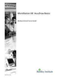
5 Section Alternative materials, design and methods of construction and equipment provides the means to resolve those issues. The key is to provide supporting documentation such as tests, research reports and sufficient evi-dence that the proposed system meets the basic principles necessary for Perimeter fire barrier protection. THE SOLUTION The Basics - EVERY listed system in the UL and Intertek (OPL) fire Resistant Directories have 5 BASIC PRINCI-PLES that MUST be applied for a suc-cessful Perimeter fire containment sys-tem: 1. Install a Reinforcement Member or a stiffener at the Safe-Off area behind the spandrel insulation to keep it from bowing due to the compression-fit of the Safing Insulation. See Fig-ure 1. 2. Mechanical attachment of the Min-eral Wool Spandrel Insulation ad-hesive attachments and friction fit applications do not work. The adhe-sive service temperature ranges from minus 30 F to plus 250 F. fire exposure tempera-tures based on ASTM E119 very quickly exceeds the adhesive service temperatures resulting in failure of the adhesive applied attachment to hold the spandrel insula-tion in place.
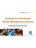
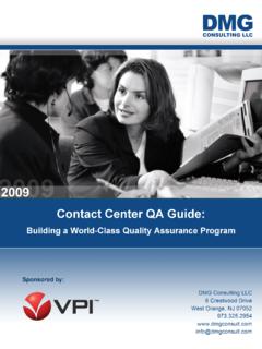
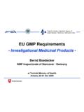
6 See Figure 2. Page 2 P E R I M E T E R F I R E C O N T AI N M E N T-T H E B A S I C S Figure 1. Basic Design Principles. 3. Protection of the mullions with mineral wool mullion covers. Aluminum begins to melt at 1220 F. See Figure 4. Without the mullion protection on the fire exposure side, the aluminum mullions and transoms will soften and melt. The mechanical attachments holding the mineral wool spandrel insulation in place will no longer be held in place allowing the spandrel and safing insulation to fall out resulting in a breach of flame and hot gasses to the floor above. See Figure 3. Page 3 Figure 3. Spiral Anchors for mullion cover attachment. P E R I M E T E R F I R E C O N T AI N M E N T-T H E B A S I C S Figure 2. Acceptable mechanical fasteners. Figure 4. ASTM E119 Time-Temperature Curve. 4. Compression fitting and orientation of the Safing Insulation. The safing insulation is compression fit (typically 25%, but varies by system ) between the slab edge and the inside face of the spandrel insulation.
7 This compression fitting of the safing insulation creates a seal that maintains its integrity preventing flame and hot gasses from breaching through to the floor above. See Figure 5. 5. Apply an approved smoke sealant material to the top of the Safing insulation to provide a smoke barrier to the sys-tem. The smoke seal is commonly spray applied to the top of the safing (non fire exposure side) forming a smoke barrier with a typical L rating or leakage rating of 0. In addition, a 1 over spray as specified, onto the floor slab and spandrel insulation creates a continuous bond that adds to holding the safing material in place during the fire and building movement. See Figure 6. Since every design is different from the previous tested system , how is a design developed so that it can meet the basic code requirements? The first step is to search for a listed system that closely resembles the curtain wall concept specified and proceed with the design listing that system .
8 When that option doesn t work, consult with the manufacturer of listed and tested systems for assistance. Manufacturers who have been involved in testing curtain wall systems for many years have extensive files and research on Perimeter fire testing of curtain walls designs. Data can be obtained as far back as the early 70 s when the development of Perimeter fire containment began. Many of today s manufacturers offer Technical Support Services that may be able to provide a solution to protect the Perimeter void, meet the code requirements, and apply the 5 basic principles. An example of manufacturer s support is Insolutions , a free service offered by Thermafiber, Inc. CONCLUSION Always follow the 5 basic principles as recommended by the International Firestop Council (IFC) for Engineering Judg-ments (EJ s) on Perimeter fire Barrier Systems. These principles apply to the known factors to maximize protection at the Perimeter of the building and minimize the interior spread of flame and hot gasses from floor to floor, keeping the first responders ( fire fighters) and the building occupants First in Life Safety.
9 ### Page 4 P E R I M E T E R F I R E C O N T AI N M E N T-T H E B A S I C S Figure 5. Safing orientation. Figure 6. Applying smoke sealant. Thermafiber, Inc. 3711 Mill Street Wabash, IN 46992 Phone: 260-563-2111 Jim Shriver has a BS in Mechanical Engineering and over 34 years experience in the construction industry. Jim is currently Corporate Director of Technical Services for Thermafiber, Inc. (formerly USG Corp.). Jim's related activities include ASTM membership and various ASTM Task Group memberships; most notably as previous Chairman of the Perimeter fire Barrier Test Standard Task Group E for including external spread of fire ( leap frog ). Present member of IFC (International Firestop Council) and Former Co-Chair of Inspection Man-ual. Jim is also a member of the AFSCC (Alliance for fire and Smoke containment and Control), and is involved in model building code development (ICC and NFPA), plus the UL and Intertek (OPL) testing coordinator for Thermafiber.
10 Jim is the author of several published articles pertaining to Perimeter fire containment . As the Director of Thermafiber's Technical Services, Jim oversees engineering designs, details and judgments specific to architectural designs for protection at the Perimeter . His designs include a patented Thermafiber Impasse system listed in the UL fire Resistance Directory. His background includes several years in manufacturing including positions as Plant Manager, Quality Manager, and Engineering Manager. References: International Code Council - International Building Code 2009, Chapter 7 fire and Smoke Protection Features, section Exterior Curtain wall/floor intersection and Chapter 1 Scope and Administration section Alternate materi-als, design and methods of construction and equipment. International Firestop Council Recommended IFC Guidelines for Evaluating Firestop Systems in Engineering Judg-ments (EJ s) Perimeter fire Barrier Systems. Annual Book of ASTM Standards, Section Four Construction E 2307-04 Standard Test Method Determining fire Re-sistance of Perimeter fire Barriers Using Intermediate-Scale, Multi-Story Test Apparatus.