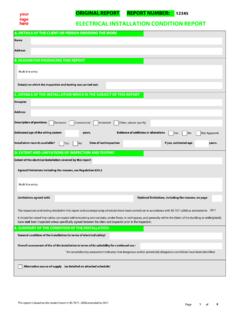
Transcription of PERIODIC INSPECTION REPORT FOR AN …
1 PERIODIC INSPECTION REPORT FOR AN ELECTRICALINSTALLATIONI ssued in accordance with British Standard BS 7671 - Requirements for electrical InstallationsReport Reference:A. DETAILS OF THE CLIENTB. PURPOSE OF THE REPORTC. DETAILS OF THE INSTALLATIOND. EXTENT OF THE installation AND LIMITATIONS OF THE INSPECTION AND TESTINGE. DECLARATIONC lient:Address:Purpose for whichthis REPORT isrequired:The REPORT must be used only for reporting on the condition of an existing :Description of premises: DomesticIndustrialCommercialOther:Estima ted age of electrical installation :yearsEvidence of alterationor additions:if yes, estimated age:yearsDate of previous INSPECTION :Records of installation available: electrical installation Certificate No or previous PERIODIC InspectionReport No:Records held by:Extent of the electrical installation covered by this REPORT :Agreed limitations, if any, on the INSPECTION and testing:This INSPECTION has been carried out in accordance with BS 7671: 2008 (IEE Wiring Regulations), as amended.
2 Cables concealed within trunking and conduits, or cables and conduits concealed under floors, in inaccessible roof spaces and generally within the fabric of the building or underground, have not been visually being the person(s) responsible for the INSPECTION and testing of the electrical installation (as indicated by my/our signatures below), particulars of which are described above (see C), having exercised reasonable skill and care when carrying out the INSPECTION and testing, hereby declare that the information in this REPORT , including the observations (see F) and the attached schedules (see H), provides an accurate assessment of the condition of the electrical installation taking into account the stated extent of the installation and the limitations of the INSPECTION and testing (see D).I/We further declare that in my/our judgement , the said installation was overall incondition (see G) at the time the INSPECTION was carried out, and that it should be further inspected as recommended (see I).
3 INSPECTION , TESTING AND ASSESSMENT BY:Name:Position:Signature:Date:Page: 1 of 6 This form is based on the model shown in Appendix 6 of BS 7671:2008 You created this PDF from an application that is not licensed to print to novaPDF printer ( )F. OBSERVATIONS AND RECOMMENDATIONS FOR ACTIONS TO BE TAKENG. SUMMARY OF THE INSPECTION AND SERVICINGR eferring to the attached schedules of INSPECTION and test results, and subject to the limitations D:There are no items adversely affecting electrical safetyorThe following observations and recommendations are madeOne of the following numbers, as appropriate, is to be allocated to each of the observations made above to indicate to the person(s)responsible for the installation the action 'requires urgent attention' or2. 'requires improvement' or3. requires further investigation' or4. 'does not comply with BS 7671:2008 (as amended)'This does not imply that the electrical installation inspected is unsafeUrgent remedial workrecommended for Items:Corrective action(s)recommended for Items:General condition of the installation :Date(s) of the INSPECTION :Overall assessment of the installation :Reference: _____ Page: 2 of 6 Item NoDescriptionCode1 This form is based on the model shown in Appendix 6 of BS 7671:2008 You created this PDF from an application that is not licensed to print to novaPDF printer ( )H.
4 SCHEDULES AND ADDITIONAL PAGESI. NEXT INSPECTIONJ. DETAILS OF THE electrical CONTRACTORK. SUPPLY CHARACTERISTICS AND EARTHING ARRANGEMENTSL. PARTICULARS OF installation AT THE ORIGINS chedule of Items Inspected and Schedules of Items Tested: Page No 4 Schedule of Circuit Details for the installation : Page No(s)Schedule of Test Results for the installation : Page No(s)Additional pages, including additional source(s) date sheets: Page No(s)The pages identified here form an essential part of this REPORT . The REPORT is valid only if accompanied by all the schedules and additional pages identified recommend that this INSPECTION is further inspected and tested after an interval of not more than:(Enter interval in terms of years, months or weeks, as appropriate)provided that any items at F which have been attributed a Recommendation Code 1 (requires urgent attention) and Code 2 (requires improvement) are remedied without delay and as soon as possible respectively.
5 Items which have been attributed a Recommendation Code 3 should be actioned as soon as practicable (see F).Trading Title:Address:Registration Number:Telephone Number:System Type(s)TN-STN-C-STNCTTITN umber and Type of Live Conductorsac:1-phase(2 wire):2-phase(3 wire):3-phase(3 wire):Other:1-phase(3 wire):3-phase(4 wire):dc:2 pole:3 pole:Other:Nature of Supply ParametersNominalvoltage(s):U:Uo:Nominal frequency, f:Prospective fault current, lpf:External earth faultloop impedance, Ze:Number of supplies:Characteristics of PrimarySupply OvercurrentProtective Device(s)BS(EN):Type:Rated current:Short-circuitcapacity:Means of EarthingDistributor'sfacility:Installati onearth electrode:Details of installation Earth Electrode (where applicable)Type:Electroderesistance, RA:Location:Method ofmeasurement:Maximum Demand (Load):Protective measure(s) against electric shock:Main Switch or Circuit-BreakerTypeBS(EN):Number ofpoles:Supplyconductorsmaterial:Supplyc onductorscsa:Voltage rating:Ratedcurrent, ln.
6 RCD operatingcurrent:RCD operatingtime:Earthing and Protective Bonding ConductorsEarthing conductorConductormaterial:Conductorcsa: Continuitycheck:Main protective bonding conductorsConductormaterial:Conductorcsa :Continuitycheck:Bonding of extraneous-conductive partsWater service:Gas service:Oil service:Structural Steel:Lightningprotection:Other services:Postcode:Reference: _____ Page: 3 of 6 VVHzkA AkA 2mmVAmAms2mm2mmThis form is based on the model shown in Appendix 6 of BS 7671:2008 You created this PDF from an application that is not licensed to print to novaPDF printer ( )SCHEDULE OF ITEMS INSPECTEDSCHEDULE OF ITEMS TESTEDM ethods of protection against electric shockBasic and fault protection:(i) SELV(ii) PELVD ouble or reinforced insulation:(iii) Double or Reinforced InsulationBasic protection:(i) Insulation oflive parts(ii) Barriers orenclosures(iii) Obstacles **(iv) Placing outof reach **Fault protection:(i) Automatic disconnection of supplyPresence of earthing conductorPresence of circuit protective conductorsPresence of main protective bonding conductorsPresence of earthing arrangements for combined protective and functional purposesPresence of adequate arrangements for alternative source(s), where applicableFELVC hoice and setting of protective and monitoring devices (for fault protection and/or overcurrent protection)(ii) Non-conducting location **Absence of protective conductors(iii) Earth-free local equipotential bonding **Presence of earth-free local equipotential bonding(iv) electrical SeparationProvided for one item of current-using equipmentProvided for more than one item of current-using equipment **Additional protection.
7 Presence of residual current device(s)Presence of supplementary bonding conductors** For use in controlled supervised/conditions onlyPrevention of mutual detrimental influence(a) Proximity of non- electrical services and other influences(b) Segregation of Band I and Band II circuits or use of Band II insulation(c) Segregation of safety circuitsIdentificationPresence of diagrams, instructions, circuit charts and similar informationPresence of danger notices and other warning noticesLabelling of protective devices, switches and terminalsIdentification of conductorsCables and ConductorsSelection of conductors for current carrying capacity and voltage dropErection methodsRouting of cables in prescribed zones or within mechanical protectionCables incorporating earthed armour or sheath, or run within an earthed wiring system, or otherwise adequatelyprotected against nails, screws and the likeAdditional protection provided by 30mA RCD for cables inconcealed walls (where required in premises not under the supervision of skilled or instructed persons)
8 Connection of conductorsPresence of fire barriers, suitable seals and protection against thermal effectsGeneralPresence and correct location of appropriate devices for isolation and switchingAdequacy of access to switchgear and other equipmentParticular protective measures for special installations and locationsConnection of single-pole devices for protection or switching in line conductors onlyCorrect connection of accessories and equipmentPresence of undervoltage protective devicesSelection of equipment and protective measures appropriate to external influencesSelection of appropriate functional switching devicesExternal earth fault loop impedance, ZeInstallation earth electrode resistance, RAContinuity of protective conductorsContinuity of ring final circuit conductorsInsulation resistance between live conductorsInsulation resistance between live conductors and earthProtection by separation of circuitsProtection against direct contact by barrier or enclosure provided during erectionInsulation of non-conducting floors or wallsPolarityEarth fault loop impedance, ZsVerification of phase sequenceOperation of residual current device(s)Functional testing of assembliesVerification of voltage dropAll boxes must be completed.
9 'tick' indicates that an INSPECTION or test was carried out and that the result was satisfactory. 'X' indicates than an INSPECTION or test was carried out and the result is not satisfactory. 'N/A' indicates that an INSPECTION or test was not applicable to the particular installation . 'LIM' indicates that, exceptionally, a limitation agreed with the person ordering the work prevented the INSPECTION or test being carried form is based on the model shown in Appendix 6 of BS 7671:2008 Reference: _____ Page: 4 of 6 You created this PDF from an application that is not licensed to print to novaPDF printer ( )CIRCUIT DETAILSCODES FOR TYPE OF WIRINGTO BE COMPLETED IN EVERY CASEL ocation of distribution board:Distribution board designation:TO BE COMPLETED ONLY IF THE DISTRIBUTION BOARD IS NOT CONNECTEDDIRECTLY TO THE ORIGIN OF THE INSTALLATIONS upply to distributionboard is from:Overcurrent protective device for thedistribution circuit:TypeBS(EN):Rating:No ofphases:NominalVoltage:Associated RCD(if any) BS(EN):RCD Noof poles:RCD ln:A: PVC/PVC cablesB: PVC cables in metallic conduitC: PVC cables in non-metallic conduitD: PVC cables in metallic trunkingE.
10 PVC cables in non-metallic trunkingF: PVC/SWA cablesG: XLPE/SWA cablesH: Mineral-insulated cablesO - Other:Reference: _____ Page: 5 of 6 AVmACircuit numberand phaseCircuit designationType of wiringReference MethodNumber ofpoints servedLivemm2 Circuitconductors:csacpcmm2 Max disconnect timepermitted by BS7671sBS(EN)Type NoRatingAOvercurrent protectivedevicesCapacitykARCDO peratingcurrentmAMaximum Zspermitted by BS7671 1 This form is based on the model shown in Appendix 6 of BS 7671:2008 You created this PDF from an application that is not licensed to print to novaPDF printer ( )CHARACTERISTICS AT THIS OF TEST INSTRUMENTSTEST RESULTSTESTED BYTO BE COMPLETED ONLY IF THE DISTRIBUTION BOARD IS NOTCONNECTED DIRECTLY TO THE ORIGIN OF THE INSTALLATIONC onfirmation of supply polarityZs:lpf:Operating timesof associated RCD(if any)At ln:At 5ln:Test Instruments (serial numbers) used:Earth fault loopimpedance:InsulationResistance:Conti nuity:RCD:Other:Other:Name(CAPITALS):Sig nature:Position:Date oftesting:Reference: _____ Page: 6 of 6 kAmsmsCircuit numberand phaser1(Line)rn(Neutral)Ring final circuits only(measured end to end)r2(cpc)R1+R2 Circuit impedances ohmsAll circuits(one column to becompleted)R2 Line/LineM Line/NeutralM Line/EarthM Insulation resistance(record lower or lowest value)Neutral/EarthM Polarity Maximummeasuredearth faultloopimpedanceZs At lnmsRCD OperatingtimesAt 5 lnms1 This form is based on the model shown in Appendix 6 of BS 7671:2008 You created this PDF from an application that is not licensed to print to novaPDF printer ( )