Transcription of PERMEABILITY TEST
1 PERMEABILITY TEST1. ObjectiveThe rate of flow of water, under laminar flow conditions, through a unit cross sectional are of soil mass,under unit hydraulic gradient, is defined as coefficient of PERMEABILITY . PERMEABILITY of the soil governsthe magnitude of excess pore water pressure built-up in the embankment or cuttings, duringconsolidation process or when the embankment is ponded by water. The excess pore water pressure in-turn significantly influences the stability of the embankments and indicate the need, or otherwise, ofneed for special measures ( sandwich construction) to prevent/quickly dissipate excess pore waterpressure. Coefficient of PERMEABILITY is used to assess drainage characteristics of soil, rate ofconsolidation and to predict rate of settlement of soil bed.
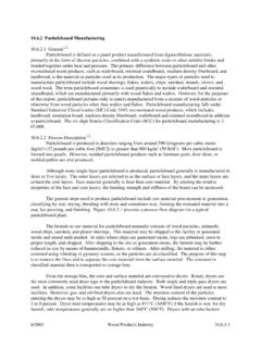
2 The coefficient of PERMEABILITY is generallydetermined by two Apparatus RequiredFig. 1: Arrangement for Constant Head PERMEABILITY (a) Permeameter mould (as per Table A),(b)Compacting equipment (A vibrating Tamper or a Sliding tamperwith a tampoing foot of 50 mm in diamter) and(c)A porous disc or suitable reinforced screen with spring attached tothe top,(d)A suitable water reservoir capable of supplying water to thePermeameter under constant head,(e)Large Funnels: These shall be fitted with special cylindrical spout,25 mm in diameter for mm maximum size particles , and 13 mmin diameter for mm maximum size particles . The length of thespout should be greater than the full length of the permeabilitychamber at least by 160 of Permeameter MouldMax.
3 ParticleSize between ISSieve Openings(mm)Min. Cylinder Diameter (mm)Not more than35% of totalSoil retainedon SieveOpeningMore than35% of totalSoil retainedon and 80- 120 and - 160 - 230 The diameter to length ratio may be about 1:23. ReferenceIS-2720(Part 36):1987 (Reaffirmed- Dec 2016) Methods of test for soils: Laboratory determination ofpermeability of granular soils (constant head) .IS-2720 (Part-17):1986 (Reaffirmed-2016) Methods of test for soils: Laboratory determination ofpermeability".4. Constant Head PERMEABILITY Test:a. Make the initial measurements and record on the data sheet, the inside diameter of the permeameter(D), the length between the manometer outlets (L) and the depth measured at four symmetricallyspaced points from the upper surface of the top plate of the PERMEABILITY cylinder to the top of the upperporous stone or screen temporarily placed on the lower porous plate or screen (H1).
4 A duplicate topplate containing four large symmetrically spaced openings through which the necessary measurementscan be made, shall be employed to determine the average value for H1. Calculate the cross sectionalarea of the specimen (A).b. A small portion of the sample selected shall be taken for water content determinations. Record theweight of the remaining air-dried sample (W1) for unit weight Place the prepared soil by one of the following procedures in uniform thin layers approximately 15 to 20mm. For fine sands, water pump grease should be applied to the cylinder wall to prevent flow of waterbetween the specimen and the wall. For coarse sand, a 7mm thickness of sponge rubber cemented tothe cylinder wall is found to be For soils having a maximum size of 10 mm or less, place the appropriate size of funnel in thepermeability device with the spout in contact with the lower porous plate or screen or previously formedlayer, and fill the funnel with sufficient soil to form a layer, taking soil from different areas of the samplein the pan.
5 Lift the funnel by 15mm or approximately the unconsolidated layer thickness to be formed,and spread the soil with a slow spiral motion, working from the perimeter of the device towards thecentre, so that a uniform layer is formed. Remix the soil in the pan for each successive layer to reducesegregation caused by taking soil from the For soils with a maximum size greater than 10 mm, spread the soil from a scoop. Turn the permeabilitycylinder sufficiently for the next scoopful, thus progressing around the inside perimeter to form auniform compacted layer of a thickness equal to the maximum particle Compact successive layers of soil to the desired relative density by appropriate procedure, to a height ofabout 20mm above the upper manometer Level the upper surface of the soil by placing the upper porous plate or screen in position and byrotating it gently clockwise and Measure and record the final height of specimen (H1 - H2)
6 , by measuring the depth from the UpperSurface of the perforated top plate employed to measure H1 to the top of the upper porous plate orscreen at four symmetrically spaced points after compressing the spring lightly to seat the porous plateor screen during the measurements; the final weight of air-dried soil used in the test (W1 - W2) byweighing the remainder of soil W2 left in the pan. Compute and record the unit weights, void ratio andrelative density of the test specimen as under:Diameter of specimen = D cmSpacing between manometer outlets = L cmLength of specimen = (H1 H2) cmArea of specimen= A = /4 x D2cm2 Volume of specimen = V = A x (H1 H2) cm3 Water content =W%Dry weight of soil specimen = Ws gDry unit weight = = Ws/V g/cm3 Specific Gravity = GsVoid ratio =e = [(Gs x w)/ ] - 1i.
7 With its gasket in place, press down the top plate against the spring and attach it securely to the top ofthe permeameter cylinder, making an airtight Connect the inlet tube of the top plate of the permeameter to a vacuum pump or suitable aspiratorcapable of evacuating the air content from the specimen and the outlet tube in the base plate to thewater container as shown in Fig. Close the manometer outlets and the outlet valve at the base plate of the permeameter. Using a vacuum pump or aspirator, evacuate the specimen under 500 mmHg, minimum for 15 minutes to remove air adhering to soil particles and from the voids. Follow the evacuation by a slow saturation of the specimen from the bottom upward under full vacuum in order to force any remaining air in the specimen.
8 Continued saturation of the specimen can be maintained more adequately by the use of de-aired water, or water maintained at an in-flow temperature sufficiently high to cause a decreasing temperature gradient in the specimen during the test. Native water or water of low mineral content should be used for the test, but in any case the fluid should be described on the report NOTE: Native water is water occurring in the rock or soil in-situ. It should be used if possible, but it (aswell as de-aired water) may need a refinement not ordinarily feasible for large scale production testingin which case available water may be used and so stated in the After the specimen has been saturated and the permeameter is full of water, close the bottom valve onthe outlet tube and disconnect the vacuum.
9 Fill the inlet tube with water from the constant-head tank byslightly opening the filter tank valve. Then connect the inlet tube to the top of the permeameter, openthe inlet valve slightly and open the manometer outlet cocks slightly, to allow water to flow, thus freeingthem of air. Connect the water manometer tubes to the manometer outlets and fill with water to removethe air. Close the inlet valve and open the outlet valve to allow the water in the manometer tubes toreach their stable water level under zero Open the inlet valve from the filter tank slightly for the first run, delay measurements of quantity of flowand head until a stable head condition without appreciable drift in water manometer level is and record the time t, head h (the difference in level in the manometers), quantity of flow Q,and water temperature Repeat the test runs at heads, increasing by 5 mm in order to establish accurately the region of laminarflow with velocity v (where v = Q/At), directly proportional to hydraulic gradient i (where i = h/L).
10 Whendepartures from the linear relation become apparent, indicating the initiation of turbulent flowconditions, 10 mm intervals of head may be used to carry the test run sufficiently along in the region ofturbulent flow to define this region if it is significant for field NOTE: Much lower values of hydraulic gradient h/L are required than generally recognized, in order toensure laminar flow conditions. The following values are suggested: loose compactness ratings h/L to ; and dense compactness ratings h/L from to ; the lower values of h/L apply to coarsersoils and the higher values to finer At the completion of the PERMEABILITY test, drain the specimen and inspect it to establish whether it wasessentially homogenous and isotropic in character.