Transcription of PESD1CAN CAN bus ESD protection diode - Nexperia
1 PESD1 CAN. CAN bus ESD protection diode Rev. 04 15 February 2008 Product data sheet 1. Product profile General description PESD1 CAN in a small SOT23 (TO-236AB) Surface-Mounted Device (SMD) plastic package designed to protect two automotive Controller Area Network (CAN) bus lines from the damage caused by electrostatic discharge (ESD) and other transients. Features n Due to the integrated diode structure only one small SOT23 package is needed to protect two CAN bus lines n Max. peak pulse power: PPP = 200 W at tp = 8/20 s n Low clamping voltage: VCL = 40 V at IPP = 1 A. n Ultra low leakage current: IRM < 1 nA. n Typ. diode capacitance matching: Cd/Cd = %. n ESD protection up to 23 kV. n IEC 61000-4-2, level 4 (ESD). n IEC 61000-4-5 (surge); IPP = 3 A at tp = 8/20 s n Small SMD plastic package Applications n CAN bus protection n Automotive applications Quick reference data Table 1.
2 Quick reference data Tamb = 25 C unless otherwise specified. Symbol Parameter Conditions Min Typ Max Unit Per diode VRWM reverse standoff voltage - - 24 V. Cd diode capacitance f = 1 MHz; VR = 0 V - 11 17 pF. Nexperia PESD1 CAN. CAN bus ESD protection diode 2. Pinning information Table 2. Pinning Pin Description Simplified outline Symbol 1 cathode 1. 3. 2 cathode 2 1. 3 common cathode 3. 2. 1 2. 006aaa155. 3. Ordering information Table 3. Ordering information Type number Package Name Description Version PESD1 CAN - plastic surface-mounted package; 3 leads SOT23. 4. Marking Table 4. Marking codes Type number Marking code[1]. PESD1 CAN *AN. [1] * = -: made in Hong Kong * = p: made in Hong Kong * = t: made in Malaysia * = W: made in China 5.
3 Limiting values Table 5. Limiting values In accordance with the Absolute Maximum Rating System (IEC 60134). Symbol Parameter Conditions Min Max Unit Per diode PPP peak pulse power tp = 8/20 s [1][2] - 200 W. IPP peak pulse current tp = 8/20 s [1][2] - 3 A. Per device Tj junction temperature - 150 C. Tamb ambient temperature 65 +150 C. Tstg storage temperature 65 +150 C. [1] Non-repetitive current pulse 8/20 s exponential decay waveform according to IEC 61000-4-5. [2] Measured from pin 1 to 3 or 2 to 3. PESD1 CAN_4 Nexperia 2017. All rights reserved Product data sheet Rev. 04 15 February 2008 2 of 12. Nexperia PESD1 CAN. CAN bus ESD protection diode Table 6. ESD maximum ratings Symbol Parameter Conditions Min Max Unit Per diode VESD electrostatic discharge voltage IEC 61000-4-2 [1][2] - 23 kV.
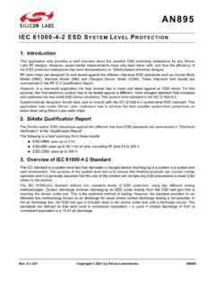
4 (contact discharge ). MIL-STD-883 ( human - 10 kV. body model ). [1] Device stressed with ten non-repetitive ESD pulses. [2] Measured from pin 1 to 3 or 2 to 3. Table 7. ESD standards compliance Standard Conditions Per diode IEC 61000-4-2; level 4 (ESD) > 15 kV (air); > 8 kV (contact). MIL-STD-883; class 3 ( human body model ) > 4 kV. 001aaa631. 001aaa630 IPP. 120. 100 %. 100 % IPP; 8 s 90 %. IPP. (%). 80. e t 50 % IPP; 20 s 40. 10 %. tr = ns to 1 ns t 0. 0 10 20 30 40 30 ns t ( s) 60 ns Fig 1. 8/20 s pulse waveform according to Fig 2. ESD pulse waveform according to IEC 61000-4-5 IEC 61000-4-2. PESD1 CAN_4 Nexperia 2017. All rights reserved Product data sheet Rev. 04 15 February 2008 3 of 12. Nexperia PESD1 CAN. CAN bus ESD protection diode 6.
5 Characteristics Table 8. Characteristics Tamb = 25 C unless otherwise specified. Symbol Parameter Conditions Min Typ Max Unit Per diode VRWM reverse standoff voltage - - 24 V. IRM reverse leakage current VRWM = 24 V - <1 50 nA. VBR breakdown voltage IR = 5 mA V. Cd diode capacitance f = 1 MHz; VR = 0 V - 11 17 pF. Cd/Cd diode capacitance [1]. matching f = 1 MHz; VR = 0 V - - %. f = 1 MHz; VR = V - - %. VCL clamping voltage [2][3]. IPP = 1 A - - 40 V. IPP = 3 A - - 70 V. rdif differential resistance IR = 1 mA - - 300 . [1] Cd is the difference of the capacitance measured between pin 1 and pin 3 and the capacitance measured between pin 2 and pin 3. [2] Non-repetitive current pulse 8/20 s exponential decay waveform according to IEC 61000-4-5.
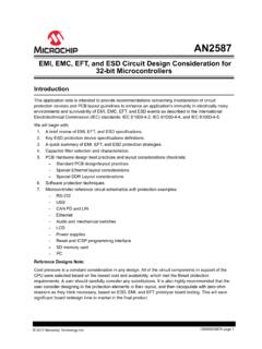
6 [3] Measured from pin 1 to 3 or 2 to 3. PESD1 CAN_4 Nexperia 2017. All rights reserved Product data sheet Rev. 04 15 February 2008 4 of 12. Nexperia PESD1 CAN. CAN bus ESD protection diode 006aaa257 001aaa193. 104 PPP PPP. (W) PPP(25 C). 103 102 10 0. 1 10 102 103 104 0 50 100 150 200. t p ( s) Tj ( C). Tamb = 25 C. Fig 3. Peak pulse power as a function of exponential Fig 4. Relative variation of peak pulse power as a pulse duration; typical values function of junction temperature; typical values 006aaa258. 20 IPP. Cd (pF). 16. 12. IR. VCL VBR VRWM IRM. IRM VRWM VBR VCL. 8 IR. 4 +. 0 IPP. 0 5 10 15 20 25. VR (V) 006aaa676. f = 1 MHz; Tamb = 25 C. Fig 5. diode capacitance as a function of reverse Fig 6. V-I characteristics for a bidirectional ESD.
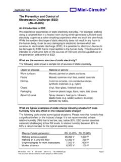
7 Voltage; typical values protection diode PESD1 CAN_4 Nexperia 2017. All rights reserved Product data sheet Rev. 04 15 February 2008 5 of 12. Nexperia PESD1 CAN. CAN bus ESD protection diode ESD TESTER 4 GHz DIGITAL. RG 223/U OSCILLOSCOPE. RZ 450 50 coax 10 . ATTENUATOR. CZ 50 . (Device IEC 61000-4-2 network Under CZ = 150 pF; RZ = 330 Test). vertical scale = 200 V/div vertical scale = 20 V/div; horizontal scale = 50 ns/div horizontal scale = 50 ns/div GND. GND. unclamped +1 kV ESD voltage waveform clamped +1 kV ESD voltage waveform (IEC 61000-4-2 network) (IEC 61000-4-2 network). vertical scale = 20 V/div; horizontal scale = 50 ns/div GND. GND. vertical scale = 200 V/div horizontal scale = 50 ns/div unclamped 1 kV ESD voltage waveform clamped 1 kV ESD voltage waveform (IEC 61000-4-2 network) (IEC 61000-4-2 network) 006aaa259.
8 Fig 7. ESD clamping test setup and waveforms PESD1 CAN_4 Nexperia 2017. All rights reserved Product data sheet Rev. 04 15 February 2008 6 of 12. Nexperia PESD1 CAN. CAN bus ESD protection diode 7. Application information The PESD1 CAN is designed for the protection of two automotive CAN bus lines from the damage caused by ESD and surge pulses. The device can be used for both, high-speed CAN bus and fault-tolerant CAN bus protection . The PESD1 CAN provides a surge capability of up to 200 W per line for an 8/20 s waveform. SPLIT. CANH. CAN BUS RT/2. TRANSCEIVER CAN. bus RT/2. CANL. Common mode choke 2 1. (optional). CG. PESD1 CAN. 3. 006aaa473. Fig 8. Typical application: ESD protection of two automotive CAN bus lines Circuit board layout and protection device placement: Circuit board layout is critical for the suppression of ESD, Electrical Fast Transient (EFT).
9 And surge transients. The following guidelines are recommended: 1. Place the PESD1 CAN as close to the input terminal or connector as possible. 2. The path length between the PESD1 CAN and the protected line should be minimized. 3. Keep parallel signal paths to a minimum. 4. Avoid running protection conductors in parallel with unprotected conductors. 5. Minimize all Printed-Circuit Board (PCB) conductive loops including power and ground loops. 6. Minimize the length of the transient return path to ground. 7. Avoid using shared transient return paths to a common ground point. 8. Ground planes should be used whenever possible. For multilayer PCBs, use ground vias. PESD1 CAN_4 Nexperia 2017. All rights reserved Product data sheet Rev.
10 04 15 February 2008 7 of 12. Nexperia PESD1 CAN. CAN bus ESD protection diode 8. Package outline 3. 1 2. Dimensions in mm 04-11-04. Fig 9. Package outline SOT23 (TO-236AB). 9. Packing information Table 9. Packing methods The indicated -xxx are the last three digits of the 12NC ordering code.[1]. Type number Package Description Packing quantity 3000 10000. PESD1 CAN SOT23 4 mm pitch, 8 mm tape and reel -215 -235. [1] For further information and the availability of packing methods, see Section 13. PESD1 CAN_4 Nexperia 2017. All rights reserved Product data sheet Rev. 04 15 February 2008 8 of 12. Nexperia PESD1 CAN. CAN bus ESD protection diode 10. Soldering 2 1. solder lands solder resist solder paste 3. occupied area Dimensions in mm (3x).