Transcription of PG-Series Batteries - Powersport | NiCd and NiMH
1 Power-Sonic has more than 39 years of battery industry experience and today our Batteries are sold in more than 70 countries world-wide. Since our inception in 1970, our focus has been the design, manufacture and marketing of rechargeable Batteries , specifically: Sealed lead-acid (SLA), also called valve regulated lead-acid (VRLA) Batteries Powersport Batteries Sealed nickel-cadmium (NiCd) and nickel-metal hydride ( nimh ) Batteries NiCd and nimh configured packs (cell assemblies) Battery ChargersOur products are widely used in an ever broadening range of electronic and industrial applications. Our Batteries continue to be used wherever cost effective and reliable DC power is required, be it as the principal power or standby power aim is the ongoing improvement of our existing products, coupled with the development of new tailored products, to meet the ever increasing needs for stand alone power. Our advanced engineering techniques and state-of-the-art manufacturing processes ensure that we remain on the cutting edge of battery technology.
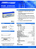
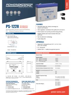
2 These skills, coupled with our selection of the finest raw materials, allow us to produce Batteries combining superior performance and our customers with reliable, yet economical, products is the cornerstone of our Voltage (V)Rated Capacity ( ) LengthWidthHeightHt. Over TerminalWeightStandard FR* FR* FR* FR* FR* FR* FR* FR* FR* FR* FR* FR* FR* FR* Specifications Tolerances are +/- Configurations16mm6mmM6T6 TerminalThreaded insert - 6mm STUD20mm6mmM6T8 TerminalThreaded insert - 6mm STUD20mm7mmM8T11 TerminalThreaded insert - 8mm STUDPG-SERIES * FR: UL94 V-0 flame retardant case & coverAll data subject to change without battery specification sheets and/or our technical manual are available for download at: BatteriesFeaturesSealed/Maintenance-Free Valve-regulated, spill-proof construction allows trouble-free, safe operation in any position. The sealed system eliminates electrolyte checking and refilling. Gases generated during charge are recombined in a unique oxygen cycle.
3 Long Service LifeThick plate design based on sturdy lead-calcium grids and advanced paste technology provide design lives of up to 10 years in standby TechnologyAbsorbent Glass Mat technology, in tandem with one-way pressure relief valves, result in efficient gas recombination and safety of operation even in severe over-charge or over discharge Internal ResistanceSuperb high-rate discharge and charge characteristics, achieved through advanced separator technology and plate composition, ensure reliable and stable performance critical in UPS and telecom Self-DischargeHigh purity lead, in conjunction with lead-calcium alloy grids, account for excellent shelf-life characteristics permitting storage for extended periods of time at 68 F (20 C) or Design - Ease of HandlingProven VRLA technology guarantees trouble-free operation and non-restricted article status for surface and air transportation under DOT (CFR-49) and IATA (A67) ConstructionHigh-impact resistant ABS plastic (UL94 V-O flame retardant) used for case and cover.
4 High internal compression ratios and innovative inter-cell weld technology impart resistance to shock, vibration, chemicals and ReliabilityCutting-edge manufacturing and process control, combined with strict quality assurance procedures, guarantee consistent and dependable applications for the PG-Series Batteries include:Standby Power Communications & Telecom Systems UPS - Uninterruptible Power Supplies Marine & Power Station Applications Back-Up for Security & Lighting Systems Access Control Devices ElevatorsPrimary Power Remote Monitoring Remote Area Power Generation Personal Transport Vehicles Geophysical Instruments & Power Tools Solar-Powered Systems Remote Access Devices Robotics Battery CapacityThe capacity of a battery is the total amount of electrical energy available from a fully charged cell. Its value depends on the discharge current, the temperature during discharge, the final (cut-off) voltage and the history of the , expressed in ampere-hours (AH), is the product of the current discharged and the length of discharge time.
5 Battery capacity varies according to the discharge rate being used. Capacity increases when discharge current is less than the 10-hr. rate and decreases when the load current is rated capacity of a Power-Sonic PG-Series battery is measured by its performance over 10 hours of constant current discharge at 68 F (20 C) to a final (cut-off) voltage of volts per battery selection for a specific application can be made from the discharge curves shown for each model if the required time and current load are detailed technical information can be obtained from our Technical Manual, which is available for download from our website at CharacteristicsBattery voltage decreases during discharge. The discharge curves in Figure 1 illustrate this for different discharge rates. C is the rated capacity of a battery. The discharge curves may be used for battery selection. It is advisable, however, to review the selection on the basis of graphs of individual data Circuit VoltageOpen circuit voltage varies according to ambient temperature and the remaining capacity of the battery.
6 Generally, open circuit voltage is determined by the specific gravity of the electrolyte. Discharging the battery lowers the specific gravity. Consequently, it is possible to determine the approximate remaining capacity of a battery from the terminal voltage. The of a Power-Sonic battery is when fully charged and when fully VoltageCut-off or final discharge voltage is the battery terminal voltage under load, in a closed circuit, to which the battery is safely discharged to maximize battery life. The appropriate cut-off voltage varies according to the actual discharge current. As a rule of thumb, high amp. loads will tolerate a lower final discharge voltage than low amp. ones with longer run times. See Table (min)(h)Discharge Time1C2C3C1530 For 2V 6V Battery1312111090 For 12V BatteryBatteryVoltage(v)Figure1:Discharg echaracteristiccurvesatvariousrates 77 F(25 C).. Capacity (%) VoltageFigure 2: Open-circuit voltage characteristicsDischarge CurrentFinal to to to to and PG-Series Table 1 : Cut-off VoltageEffects of TemperatureActual capacity is a function of ambient temperature and rate of discharge.
7 At 68 F (20 C) rated capacity is 100%. Above this temperature capacity increases, below it capacity decreases as temperature falls. While raising ambient temperatures increases capacity, it also decreases useful service life. It is estimated that battery life is halved for each 18 F (10 C) above normal room UseThe number of charge/discharge cycles depends on the capacity taken from the battery - a function of discharge rate and depth of discharge - operating temperature and the charging 3 shows the relationship between depth of discharge and number of cycles, but also the capacity increases during the early UseThe float service life, or the life expectancy under continuous charge, depends on the frequency and depth of discharge, the charge voltage and the ambient a float voltage of V/cell and an ambient temperature of 68-77 F (20-25 C), PG-Series 6V & 12V Batteries are designed to yield a service life of up to 10 years before the capacity drops to about 60%.
8 The graph in Figure 5 shows life characteristics in float (standby) service for ambient temperatures ranging from 60-130 F (15-55 C).Figure3 of Cycles10080604020020040060080010001200 DischargeDepth 100%DischargeDepth 50%DischargeDepth 30%1. Discharge Current: (Final Voltage V/cell)2. Charge Current: Ambient Temperature: 20 C to 25 C(68 F to 77 F)Capacity (%)100806040200 YearsAmbientTemperature20 C(68 F) :LifecharacteristicsinstandbyuseRetentio nCapacityRatio(%)If prevailing ambient temperatures are well above 68-77 F (20-25 C) the life expectancy of this type of battery in float service depends greatly on temperature compensated charging. The typical temperature coefficient is -3mV/cell/ C. The graph in Figure 5 is based on temperature compensated :Servicelifeatvariousambienttemperatures 20 30 40 50 60 2010 Temperature(C )End of life defined as 60%of rated capacityServiceLife(Years) (oC)Percent(%) of C1 C0 Figure 6: Effects of temperature on capacityPG-Series Batteries Shelf Life and StorageSpecial alloy electrodes and high purity lead impart low self-discharge rates and, consequently, a long shelf life.
9 The rate of self-discharge is approximately 3% per month when Batteries are stored at 68 F (20 C). At low temperatures it is nearly negligible, at higher ones self-discharge maximize battery life and performance: Recharge after each use Do not store in a discharged state Store at 68 F (20 C) or lower Recharge every 6 months if not usedChargingDependable performance and long service life depend upon correct charging. Faulty procedures or inadequate charging equipment, result in decreased battery life and/or unsatisfactory performance. The selection of suitable charging circuits and methods is as important as choosing the right battery for the charge a Power-Sonic battery, a DC voltage higher than the open-circuit voltage of is applied to the terminals of the battery. Depending on the state of charge, the cell may temporarily be lower (after discharge) or higher (immediately after charging) than Batteries may be charged by using any of the conventional charging techniques.
10 To obtain maximum service life and capacity, along with acceptable recharge time and economy, constant voltage-current limited charging is Voltage ChargingConstant voltage - current limited charging is the recommended charging method for Power-Sonic Batteries . Care must be taken to adhere to the charge voltage and initial charge current Current ChargingIt is generally not a recommended charge method. It is, however, an effective method for occasional boost-charging of Batteries in series after extended storage or prior to a capacity verification. Charge time must be strictly controlled to avoid detrimental ChargingThis is the simplest, least expensive charging method. Either quasi-constant voltage or quasi-constant current characteristics can be built into the charger through combination of transformer, diode and resistance. Of the two, constant potential charging is ApplicationsIn this set-up the battery and the load are connected in parallel with the rectified power source.