Transcription of PHYSICS EXPERIMENTS - Weebly
1 1 PHYSICS EXPERIMENTS Imagination is more important than knowledge. - Albert Einstein The only thing that interferes with my learning is my education. - Albert Einstein Two things are infinite: the universe and human stupidity; and I'm not sure about the universe. - Albert Einstein 2 LEAVING CERTIFICATE PHYSICS LISTED EXPERIMENTS CONTENTS MECHANICS Measurement of velocity .. 4 and acceleration .. 6 To show that a proportional to F .. 8 Verification of the principle of conservation of momentum .. 10 Measurement of g .. 12 Verification of Boyle s law .. 14 Investigation of the laws of equilibrium for a set of co-planar forces .. 16 Investigation of the relationship between period and length for a simple pendulum and hence calculation of g* .. 18 HEAT Calibration curve of a thermometer using the laboratory mercury thermometer as a standard.
2 20 Measurement of the specific heat capacity of a metal by an electrical method .. 22 of water by an electrical method .. 24 of a metal or water by a mechanical method .. 26 Measurement of the specific latent heat of fusion of ice .. 28 Measurement of the specific latent heat of vaporisation of water .. 30 SOUND Measurement of the speed of sound in air .. 32 Investigation of the variation of fundamental frequency of a stretched string with length .. 35 Investigation of the variation of the fundamental frequency of a stretched string with tension* .. 37 LIGHT Measurement of the focal length of a concave mirror .. 39 Verification of Snell s law of refraction .. 41 Measurement of the refractive index of a liquid .. 43 Measurement of the focal length of a converging lens .. 45 Measurement of the wavelength of monochromatic light .. 47 (using the laser) .. 49 ELECTRICITY Verification of Joule s law (as I 2).
3 51 To measure the resistivity of the material of a wire .. 53 To investigate the variation of the resistance of a metallic conductor with temperature .. 55 To investigate the variation of the resistance of a thermistor with temperature .. 57 3 To investigate the variation of current (I) with (V) for (a) metallic conductor .. 58 (b) filament bulb .. 59 (c) copper sulfate solution with copper electrodes .. 60 (d) semiconductor diode .. 61 APPENDIX To estimate the specific heat capacity of water .. 63 To estimate the specific latent heat of vaporisation of water .. 64 Measurement of the focal length of a concave mirror (approximate method) .. 65 Measurement of the focal length of a converging lens (approximate method) .. 65 Demonstration of standing waves .. 66 The rota option .. 68 experiment at Higher Level only* 4 MEASUREMENT OF VELOCITY Apparatus Ticker timer and tape, suitable low-voltage power supply, trolley, runway, laboratory jack or stand.
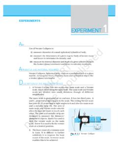
4 Procedure 1. Set up the apparatus as in the diagram. 2. Connect the ticker timer to a low-voltage power supply. 3. Give the trolley a small push to start it moving. 4. Adjust the angle of inclination of the runway until the trolley moves with constant velocity the spots on the tape are all equidistant. 5. Most ticker timers make 50 spots per second. Therefore the time interval between two adjacent spots is s. 6. Measure the length s of ten adjacent spaces. 7. The time t is 10 = s. 8. As the trolley was travelling at constant velocity we can say that tsv . 9. Repeat using pushes of varying strengths. 10. Tabulate results as shown. s/m t/s v/m s-1 Results .. s Ticker tape Trolley Ticker timer Runway 5 Notes Ignore the initial five or six dots on the tape as this shows the initial acceleration due to the push. Ticker timers that use precarbonated tape are recommended because the friction due to paper drag is reduced.
5 Ensure that the voltage rating of the timer is not exceeded. Some timers make one hundred dots in one second. 6 MEASUREMENT OF ACCELERATION Apparatus Ticker timer and tape, suitable low-voltage power supply, dynamics trolley, runway and laboratory jack or stand. Procedure 1. Set up the apparatus as in the diagram. 2. Connect the ticker timer to a suitable low-voltage power supply. 3. Allow the trolley to roll down the runway. 4. The trolley is accelerating as the distance between the spots is increasing. 5. The time interval between two adjacent dots is s, assuming the ticker timer marks fifty dots per second. 6. Mark out five adjacent spaces near the beginning of the tape. Measure the length s1. 7. The time t1 is 5 = s. 8. We can assume that the trolley was travelling at constant velocity for a small time interval. Thus uts 11timedistance velocity Initial.
6 9. Similarly mark out five adjacent spaces near the end of the tape and find the final velocity v. 10. Measure the distance s in metres from the centre point of u to the centre point of v. 11. The acceleration is found using the formula suva222 . 12. By changing the tilt of the runway different values of acceleration are obtained. Repeat a number of times. 13. Tabulate results as shown. s1/m t1/s u/m s-1 s2/m t2/s v/m s-1 t/s a/m s-2 .. Ticker timer Ticker tape Trolley Runway 7 Results Notes Ignore the initial five or six dots on the tape since the trolley may not be moving with constant acceleration during this time interval. Ticker timers that use precarbonated tape are recommended because the friction due to paper drag is reduced. Ensure that the voltage rating of the timer is not exceeded. Some timers make one hundred dots in one second. 8 TO SHOW THAT a F Apparatus Air-track with one vehicle, pulley and blower, two photogates, two retort stands, dual timer, metre-stick, black card, set of slotted weights (1 N total).
7 Procedure 1. Set up the apparatus as in the diagram. Make sure the card cuts both light beams as it passes along the track. 2. Level the air track. 3. Set the weights F at 1 N. With the card at one end of the track start the blower and release the card from rest. 4. Note the times t1 and t2. 5. Remove one N disc from the slotted weight, store this on the vehicle, and repeat. 6. Continue for values of F from N to N. 7. Use a metre-stick to measure the length of the card l and the separation of the photogate beams s. 8. Record results as shown. 9. Draw a graph of a/m s-2 against F/N. Slotted weights Dual timer Photogate Air track Card Light beam Pulley l t1 t2 s 9 Results l = .. m. s = .. m. Initial velocity 1tlu Final velocity 2tlv Acceleration asuv222 F/N t1/s t2 /s u/m s-1 v/m s-1 a/m s-2 Conclusion A straight line through the origin shows that, for a constant mass, the acceleration is proportional to the applied force.
8 Notes The total accelerating mass must be kept constant; hence the need to transfer the masses. Block the ten pairs of air holes nearest the buffer/pulley end of the track with cellotape. This part of the track will now act as a brake on the vehicle. Occasionally check the air holes on the linear air-track with a pin, to clear any blockages due to grit or dust. This experiment may be performed using a trolley on a friction-compensated ramp. 10 VERIFICATION OF THE PRINCIPLE OF CONSERVATION OF MOMENTUM Apparatus Linear air-track, two vehicles with velcro pads attached, blower, two photogates, two retort stands, dual timer, metre-stick, black card. Procedure 1. Set up apparatus as in the diagram. 2. Connect air-track to blower. 3. Level the air-track. 4. Measure the mass of each vehicle m1 and m2 respectively, including attachments, using a balance.
9 5. Measure the length l of the black card in metres. 6. With vehicle 2 stationary, give vehicle 1 a gentle push. After collision the two vehicles coalesce and move off together. 7. Read the transit times t1and t2 for the card through the two beams. 8. Calculate the velocity before the collision, 1tlu . 9. Calculate the velocity after the collision, 2tlv . 10. Calculate the momentum before the collision, pbefore = m1u and the momentum after the collision, pafter = (m1 + m2) v. 11. Repeat several times, with different velocities and different masses. 12. Record results as shown. Velcro pad Dual timer Photogate Air track t1 t2 Light beam Card l Vehicle 1 Vehicle 2 11 Results Mass of vehicle 1, m1 =.. kg. Mass of vehicle 2, m2 =.. kg. s1/m t1/s u/m s-1 pbefore / kg m s-1 s2/m t2/s v/m s-1 pafter / kg m s-1 Notes To see if the track is level carry out these tests: a) A vehicle placed on a level track should not drift toward either end.
10 B) When a vehicle is travelling freely along a level track, the times recorded on both timers should be equal. This holds for travel in either direction. Adding small weights, magnets or putty will change the masses of the vehicles. Block the ten pairs of air holes nearest the buffer end of the track with cellotape. This part of the track will now act as a brake on the vehicle. Occasionally check the air holes on the linear air-track with a pin, to clear any blockages due to grit or dust. This experiment may be performed using trolleys on a friction-compensated ramp. 12 MEASUREMENT OF g Apparatus Millisecond timer, metal ball, trapdoor and electromagnet. Procedure 1. Set up the apparatus. The millisecond timer starts when the ball is released and stops when the ball hits the trapdoor. 2. Measure the height h as shown, using a metre stick.