Transcription of PIC Assembly Language for the Complete Beginner
1 PIC Assembly Language for theComplete BeginnerMichael A. CovingtonArtificial Intelligence CenterThe University of GeorgiaAthens, Georgia 30602-7415 article appeared inElectronics NowMagazine in 1999 and isreprinted here by permission. Some web addresses have been up-dated but the content has not; you will find that MPLAB, for instance,now looks somewhat may print out this article for personal use but not for further 1999 Gernsback Publications, 1999, 2004 Michael A. days, the field of electronics is divided into haves and have-nots people who can program microcontrollers and people who can you re one of the have-nots, this article is for are one-chip computers designed to control other equip-ment, and almost all electronic equipment now uses them.
2 TheaverageAmerican home now contains about 100 computers, almost all of whichare microcontrollers hidden within appliances, clocks, thermostats, andeven automobile some microcontrollers can be programmed in C or BASIC,you need Assembly Language to get the best results with the least expensivemicros. The reason is that Assembly Language lets you specify the exactinstructions that the CPU will follow; you can control exactly how muchtime and memory each step of the program will take. On a tiny computer,this can be important. What s more, if you re not already an experiencedprogrammer, you may well find that Assembly Language issimplerthanBASIC or C.
3 In many ways it s more like designing a circuit than trouble with Assembly Language is that it s different for each kindof CPU. There s one Assembly Language for Pentiums, anotherfor PIC mi-crocontrollers, still another for Motorola 68000s, and so forth. There areeven slight differences from one model of PIC to another. Andthat leadsto a serious problem each Assembly - Language manual seems to assumethat you already know the Assembly Language for some other processor!So as you look from one manual to another in puzzlement,there s no wayto get s the problem this article will address. I won t teach you all ofPIC Assembly Language , just enough to get you started.
4 For concreteness,I ll use just one processor, the PIC16F84. To be very precise, I ll use the2 PIC16F84-04P, which operates up to 4 MHz and is housed in a plastic is a product of Microchip, Inc. (Chandler, Arizona), and it sclosely related to the rest of the PIC family which, however, I ll ignore toprevent do the experiments described in this article, you ll needone or morePIC16F84-04P chips; we strongly recommend having more thanone soyou can rule out a damaged PIC if your circuit doesn t work. You ll alsoneed the other parts for the circuits you want to build (see the schematics).And you ll need a PC-compatible personal computer, the MPASM assem-bler software (which you can download ),and a PIC programmer such as Ramsey Electronics PICPRO-1 or theNOPPP programmer published in this magazine, September 1998, anddescribed The PIC16F8 Xdata sheet, actually a 122-page manual, will also come in handy; it s calledPIC16F8X because it covers both PIC16F84 and PIC14F83, and you candownload it or request a printed copy from PART 1 - MEET THE What s inside a PIC?
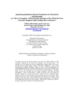
5 Figure 1 shows the pinout of the PIC16F84, and Figure 2 shows the mostimportant parts inside. The PIC is a tiny but Complete computer. It has aCPU (central processing unit), program memory (PROM), working mem-1 Note added 2004: The 10-MHz version is now more common and will work in all thesame 2 3 4 5 6 18 17 16 15 14 13 A2 A3 A4 MCLR GND B0 B7 V+ O2 O1 A0 A1 12 11 10 7 8 9 B1 B2 B3 B4 B5 B6 PIC16F84 Figure 1: Pinout of (RAM), and two input-output CPU is, of course, the brain of the computer. It reads and exe-cutes instructions from the program memory. As it does so, itcan store andretrieve data in working memory (RAM). Some CPUs make a distinctionbetween registers located within the CPU and RAM located outsideit; the PIC doesn t, and its general-purpose working RAM is also knownas file registers.
6 On the F84, there are 68 bytes of general-purpose RAM,located at addresses hex 0C to hex the general-purpose memory, there is a special working regis-ter or W register where the CPU holds the data it s workingon. Thereare also several special-function registers each of which controls the oper-4ation of the PIC in some program memory of the F84 consists of flash EPROM; it can berecorded and erased electrically, and it retains its contents when pow-ered off. Many other PICs require ultraviolet light for erasure and are noterasable if you buy the cheaper version without the quartz window. The F84, however, is always erasable and are two input-output ports, port A and port B, and each pin ofeach port can be set individually as an input or an output.
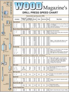
7 Thebits ofeach port are numbered, starting at 0. In output mode, bit 4 ofport A hasan open collector (or rather open drain); the rest of the outputs are regularCMOS. (Working with microcontrollers, you have to rememberdetails likethis; there s no programming Language or operating system to hide thedetails of the hardware from you.) The CPU treats each port asone 8-bitbyte of data even though only five bits of port A are actually brought outas pins of the REGISTER O1 O2 14 - BIT BUS 8 - BIT BUS B0 SPECIAL FUNCTION REGISTERS PROGRAM MEMORY (FLASH EPROM) FILE REGISTERS (RAM) CPU CLOCK OSCILLATOR PORT B B1 B2 B3 B4 B5 B6 B7 A0 A1 A2 A3 CMOS INPUTS AND OUTPUTS PORT A A4 Figure 2: Main components of the inputs are CMOS-compatible; PIC outputs can drive TTL orCMOS logic chips.
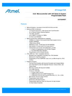
8 Each output pin can source or sink 20 mA as long asonly onepin is doing so at a time. Further information about electrical limits isgiven in the PIC16F84 data F84 also has some features we won t be using, including an EEP-ROM for long-term storage of data, an onboard timer-countermodule,and optional pull-up resistors on port Power and clock requirementsThe PIC16F84 requires a 5-volt supply; actually, any voltage from volts will do fine, so you can run it from three cells. Figure3 shows several power-supply options. The PIC consumes only1 mA even less, at low clock speeds but the power supply must alsoprovidethe current flowing through LEDs or other high-current devices that thePIC may be driving.
9 Thus, the last circuit, with the Zener diode, is onlyfor PICs that aren t driving four power supply circuits rely on a F capacitor from pin 14(V+) to ground, mounted close to the PIC, to protect the PIC and adja-cent components from electrical noise. This capacitor should be presentno matter how clean you think your DC supply MCLR pin is normally connected to V+ through a 10k it momentarily will clear RAM and reset the PIC. Ifyour powersupply voltage comes up slowly, the PIC may start up in a confused state;in that case you should add a normally-open reset button fromMCLR OUT GND 7805 OR 78L05 ON/ OFF ON/ OFF 1N4001 +7V TO 20V + + + 6V OR FOUR IN SERIES 1K 1N4733A ( ) + (SEE NOTE) +6V TO 20V 4 5 14 MCLR GND V+ PIC16F84 10K F +4V TO 6V Figure 3: Some ways to power a PIC.
10 The last one is only for a PICthat isnot powering an LED or other high-current any CPU, the PIC needs a clock an oscillator to control the speedof the CPU and step it through its operations. The maximum clock fre-quency of the PIC16F84-04P is, as already noted, 4 MHz. Thereis no lowerlimit. Low clock frequencies save power and reduce the amount of count-ing the PIC has to do when timing a slow operation. At 30 kHz, a PIC canrun on 4 shows the most popular clock circuits. The clock signal can befed in from an external source, or you can use the PIC s on-board oscilla-tor with either a crystal or a resistor and capacitor. Crystals are preferredfor high accuracy; crystals, mass-produced for color TV circuits,work well and are very cheap.