Transcription of PIC24FV32KA304 Family Data Sheet - Microchip Technology
1 PIC24FV32KA304 Family . 20/28/44/48-Pin, General Purpose, 16-Bit Flash Microcontrollers with XLP Technology Power Management Modes Peripheral Features Run CPU, Flash, SRAM and Peripherals On Hardware Real-Time Clock and Calendar (RTCC): Doze CPU Clock Runs Slower than Peripherals - Provides clock, calendar and alarm functions Idle CPU Off, Flash, SRAM and Peripherals On - Can run in Deep Sleep mode Sleep CPU, Flash and Peripherals Off, and - Can use 50/60 Hz power line input as clock SRAM On source Deep Sleep CPU, Flash, SRAM and Programmable 32-Bit Cyclic Redundancy Check Most Peripherals Off; Multiple Autonomous (CRC). Wake-up Sources Multiple Serial Communication modules: Low-Power Consumption: - Two 3/4-wire SPI modules - Run mode currents down to 8 A, typical - Two I2C modules with multi-master/slave support - Idle mode currents down to A, typical - Two UART modules, supporting RS-485, - Deep Sleep mode currents down to 20 nA, RS-232, LIN/J2602, IrDA.
2 Typical Five 16-Bit Timers/Counters with Programmable - Real-Time Clock/Calendar currents down to Prescaler: 700 nA, 32 kHz, - Can be paired as 32-bit timers/counters - Watchdog Timer is 500 nA, typical Three 16-Bit Capture Inputs with Dedicated Timers High-Performance CPU Three 16-Bit Compare/PWM Outputs with Modified Harvard Architecture Dedicated Timers Up to 16 MIPS Operation @ 32 MHz Configurable Open-Drain Outputs on Digital I/O. Pins 8 MHz Internal Oscillator with 4x PLL Option and Multiple Divide Options Up to Three External Interrupt Sources 17-Bit by 17-Bit Single-Cycle Hardware Multiplier 32-Bit by 16-Bit Hardware Divider, 16-Bit x 16-Bit Working Register Array C Compiler Optimized Instruction Set Architecture 2011-2017 Microchip Technology Inc.
3 DS30009995E-page 1. PIC24FV32KA304 Family . Analog Features Special Microcontroller Features 12-Bit, Up to 16-Channel Analog-to-Digital Wide Operating Voltage Range: Converter: - to (PIC24F devices). - 100 ksps conversion rate - to (PIC24FV devices). - Conversion available during Sleep and Idle Low-Power Wake-up Sources and Supervisors: - Auto-sampling, timer-based option for Sleep - Ultra Low-Power Wake-up (ULPWU) for and Idle modes Sleep/Deep Sleep - Wake on auto-compare option - Low-Power Watchdog Timer (DSWDT) for Deep Sleep dual Rail-to-Rail Analog comparators with - Extreme Low-Power Brown-out Reset (DSBOR) for Programmable Input/Output Configuration Deep Sleep, LPBOR for all other modes On-Chip Voltage Reference System Frequency Range Declaration bits: Internal Temperature Sensor - Declaring the frequency range optimizes the Charge Time Measurement Unit (CTMU).
4 Current consumption. - Used for capacitance sensing, 16 channels Standard Watchdog Timer (WDT) with On-Chip, - Time measurement, down to 200 ps Low-Power RC Oscillator for Reliable Operation resolution Programmable High/Low-Voltage Detect (HLVD). - Delay/pulse generation, down to 1 ns Standard Brown-out Reset (BOR) with resolution 3 Programmable Trip Points that can be Disabled in Sleep High-Current Sink/Source (18 mA/18 mA) on All I/O Pins Flash Program Memory: - Erase/write cycles: 10,000 minimum - 40 years' data retention minimum Data EEPROM: - Erase/write cycles: 100,000 minimum - 40 years' data retention minimum Fail-Safe Clock Monitor (FSCM).
5 Programmable Reference Clock Output Self-Programmable under Software Control In-Circuit Serial Programming (ICSP ) and In-Circuit Debug (ICD) via 2 Pins Compare/PWM. 12-Bit A/D (ch). Memory comparators CTMU (ch). UART w/. Capture Output Timers 16-Bit RTCC. IrDA . Input Program Pins PIC24F. EE Data SPI. (bytes). (bytes). (bytes). I2C. SRAM. Flash Device PIC24FV16KA301/ 20 16K 2K 512 5 3 3 2 2 2 12 3 12 Y. PIC24F16KA301. PIC24FV32KA301/ 20 32K 2K 512 5 3 3 2 2 2 12 3 12 Y. PIC24F32KA301. PIC24FV16KA302/ 28 16K 2K 512 5 3 3 2 2 2 13 3 13 Y. PIC24F16KA302. PIC24FV32KA302/ 28 32K 2K 512 5 3 3 2 2 2 13 3 13 Y. PIC24F32KA302. PIC24FV16KA304/ 44 16K 2K 512 5 3 3 2 2 2 16 3 16 Y.
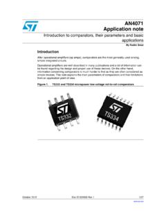
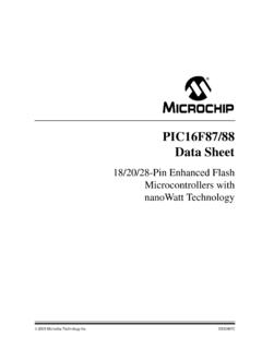
6 PIC24F16KA304. PIC24FV32KA304 / 44 32K 2K 512 5 3 3 2 2 2 16 3 16 Y. PIC24F32KA304. DS30009995E-page 2 2011-2017 Microchip Technology Inc. PIC24FV32KA304 Family . Pin Diagrams 20-Pin SPDIP/SSOP/SOIC(1) MCLR/RA5 1 20 VDD. RA0 2 19 VSS. 24 FVXXKA301. 24 FXXKA301. RA1 3 18 RB15. RB0 4 17 RB14. RB1 5 16 RB13. RB2 6 15 RB12. RA2 7 14 RA6 or VCAP. RA3 8 13 RB9. RB4 9 12 RB8. RA4 10 11 RB7. Pin Features Pin PIC24 FVXXKA301 PIC24 FXXKA301. 1 MCLR/VPP/RA5 MCLR/VPP/RA5. 2 PGEC2/VREF+/CVREF+/AN0/C3 INC/SCK2/CN2/RA0 PGEC2/VREF+/CVREF+/AN0/C3 INC/SCK2/CN2/RA0. 3 PGED2/CVREF-/VREF-/AN1/SDO2/CN3/RA1 PGED2/CVREF-/VREF-/AN1/SDO2/CN3/RA1. 4 PGED1/AN2/ULPWU/CTCMP/C1 IND/C2 INB/C3 IND/U2TX/SDI2/ PGED1/AN2/ULPWU/CTCMP/C1 IND/C2 INB/C3 IND/U2TX/SDI2/.
7 OC2/CN4/RB0 OC2/CN4/RB0. 5 PGEC1/AN3/C1 INC/C2 INA/U2RX/OC3/CTED12/CN5/RB1 PGEC1/AN3/C1 INC/C2 INA/U2RX/OC3/CTED12/CN5/RB1. 6 AN4/SDA2/T5CK/T4CK/U1RX/CTED13/CN6/RB2 AN4/SDA2/T5CK/T4CK/U1RX/CTED13/CN6/RB2. 7 OSCI/AN13/C1 INB/C2 IND/CLKI/CN30/RA2 OSCI/AN13/C1 INB/C2 IND/CLKI/CN30/RA2. 8 OSCO/AN14/C1 INA/C2 INC/CLKO/CN29/RA3 OSCO/AN14/C1 INA/C2 INC/CLKO/CN29/RA3. 9 PGED3/SOSCI/AN15/U2 RTS/CN1/RB4 PGED3/SOSCI/AN15/U2 RTS/CN1/RB4. 10 PGEC3/SOSCO/SCLKI/U2 CTS/CN0/RA4 PGEC3/SOSCO/SCLKI/U2 CTS/CN0/RA4. 11 U1TX/C2 OUT/OC1/IC1/CTED1/INT0/CN23/RB7 U1TX/INT0/CN23/RB7. 12 SCL1/U1 CTS/C3 OUT/CTED10/CN22/RB8 SCL1/U1 CTS/C3 OUT/CTED10/CN22/RB8.
8 13 SDA1/T1CK/U1 RTS/IC2/CTED4/CN21/RB9 SDA1/T1CK/U1 RTS/IC2/CTED4/CN21/RB9. 14 VCAP C2 OUT/OC1/IC1/CTED1/INT2/CN8/RA6. 15 AN12/HLVDIN/SCK1/SS2/IC3/CTED2/INT2/CN14 /RB12 AN12/HLVDIN/SCK1/SS2/IC3/CTED2/CN14/RB12 . 16 AN11/SDO1/OCFB/CTPLS/CN13/RB13 AN11/SDO1/OCFB/CTPLS/CN13/RB13. 17 CVREF/AN10/C3 INB/RTCC/SDI1/C1 OUT/OCFA/CTED5/INT1/ CVREF/AN10/C3 INB/RTCC/SDI1/C1 OUT/OCFA/CTED5/INT1/. CN12/RB14 CN12/RB14. 18 AN9/C3 INA/SCL2/T3CK/T2CK/REFO/SS1/CTED6/CN11/R B15 AN9/C3 INA/SCL2/T3CK/T2CK/REFO/SS1/CTED6/CN11/R B15. 19 VSS/AVSS VSS/AVSS. 20 VDD/AVDD VDD/AVDD. Legend: Pin numbers in bold indicate pin function differences between PIC24FV and PIC24F devices.
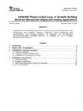
9 Note 1: PIC24F32KA304 device pins have a maximum voltage of and are not 5V tolerant. 2011-2017 Microchip Technology Inc. DS30009995E-page 3. PIC24FV32KA304 Family . Pin Diagrams 28-Pin SPDIP/SSOP/SOIC(2). MCLR/RA5 1 28 VDD. RA0 2 27 Vss RA1 3 26 RB15. PIC24 FVXXKA302. PIC24 FXXKA302. RB0 4 25 RB14. RB1 5 24 RB13. RB2 6 23 RB12. RB3 7 22 RB11. VSS 8 21 RB10. RA2 9 20 RA6 or VCAP. RA3 10 19 RA7. RB4 11 18 RB9. RA4 12 17 RB8. VDD 13 16 RB7. RB5 14 15 RB6. Pin Features Pin PIC24 FVXXKA302 PIC24 FXXKA302. 1 MCLR/VPP/RA5 MCLR/VPP/RA5. 2 VREF+/CVREF+/AN0/C3 INC/CTED1/CN2/RA0 VREF+/CVREF+/AN0/C3 INC/CTED1/CN2/RA0. 3 CVREF-/VREF-/AN1/CN3/RA1 CVREF-/VREF-/AN1/CN3/RA1.
10 4 PGED1/AN2/ULPWU/CTCMP/C1 IND/C2 INB/C3 IND/U2TX/CN4/RB0 PGED1/AN2/ULPWU/CTCMP/C1 IND/C2 INB/C3 IND/U2TX/CN4/RB0. 5 PGEC1/AN3/C1 INC/C2 INA/U2RX/CTED12/CN5/RB1 PGEC1/AN3/C1 INC/C2 INA/U2RX/CN5/RB1. 6 AN4/C1 INB/C2 IND/SDA2/T5CK/T4CK/U1RX/CTED13/CN6/RB2 AN4/C1 INB/C2 IND/SDA2/T5CK/T4CK/U1RX/CTED13/CN6/RB2. 7 AN5/C1 INA/C2 INC/SCL2/CN7/RB3 AN5/C1 INA/C2 INC/SCL2/CN7/RB3. 8 VSS VSS. 9 OSCI/AN13/CLKI/CN30/RA2 OSCI/AN13/CLKI/CN30/RA2. 10 OSCO/AN14/CLKO/CN29/RA3 OSCO/AN14/CLKO/CN29/RA3. 11 SOSCI/AN15/U2 RTS/CN1/RB4 SOSCI/AN15/U2 RTS/CN1/RB4. 12 SOSCO/SCLKI/U2 CTS/CN0/RA4 SOSCO/SCLKI/U2 CTS/CN0/RA4. 13 VDD VDD. 14 PGED3/ASDA(1)/SCK2/CN27/RB5 PGED3/ASDA(1)/SCK2/CN27/RB5.