Transcription of Picture Report for Maersk Jabal - Eureka Control Systems
1 Page 1 of 16 Picture Report for Maersk Jabal Vessel Name: Maersk Jabal Customer: Maersk line Ship Mgnt. Location: Keppel shipyard & Anchorage Date: 26 Mar 2016 to 06 April 2016 Jobs Description: To check and service on the following Systems -15ppm monitor calibration -Fire alarm system condition check -Cargo Hold Bilge Alarm System - fuel Oil Flowmeters to service calibrate - To install new fuel oil Leakage Alarm System REPORTS: We attended the vessel at Keppel shipyard, discussed with the attending supt and started the paperworks with the shipyard. Since there was only few days left before the vessel sail. We had to start work the following day itself. Page 2 of 16 AA) 15 ppm Calibration Make: Georim Engineering co. ltd Model: GBA-155 Serial no: GBA-155-215 Herewith below is the Picture of the 15ppm unit installed on board the vessel.
2 The unit had been 15ppm monitor Analysing unit The unit has been successfully tested the 000ppm with clean water and tested the 15ppm alarm using the test tube provided from the maker itself. Page 3 of 16 When testing the 15 ppm alarm to second engineer and also ch engineer, we also tested the 3 way valve and found satisfactory. The system is now calibrated and tested to satisfactory and now ready for operation. BB) Fire Alarm System Make: Autronica Auto- Safe Model: Version: As requested by supt. for us to check the complete fire alarm system and submit condition and recommendation Report . Therefore, our guys start to check and test the complete system. Herewith below the type of fire alarm panel installed on board. The system consist of total 4 loops and 124 sensors and call points. Page 4 of 16 Picture above indicating the main fire alarm Control panel.
3 Picture beside indicating manual call point type. Page 5 of 16 Picture indicating the type of smoke sensor used for the system We tested and simulated all 4 loops, fire alarm, disable/enable function and found all working properly. Loop 1 we tested total 52 no s sensors and call point. Found all sensors and some call points working good except for the following manual call points A62, poop deck corridor (manual call point) A63, poop deck emergency d/g room (manual call point) A70, poop deck corridor (manual call point) A81, main deck CO2 room (manual call point) A82, main deck changing room (manual call point) Loop 2 we tested total 50 no s sensor and call point, found the following below faulty and need replacement. B03, casing deck (manual call point) B06, poop deck E/R entrance (manual call point) B09, E/R 2nd deck, M/E stairway (manual call point) Page 6 of 16 B16, E/R 2nd deck, S/G room entrance (manual call point) B24, E/R 2nd deck, spare M/E cylinder (smoke detector) B43, E/R 3rd deck floor, M/E stairway stbd (manual call point) B63, E/R floor, stairway stbd (manual call point) B67, E/R floor, emergency exit (manual call point) Loop 3 we tested total 09 sensors and call points.
4 The following found faulty and require replacement. C11, B/S bow thruster room (manual call point) Loop 4 we tested total 13 no s sensors and call points and found all working in good condition. In order to get the system complete operational, we will require to renew all the faulty items and must be addressed by maker before delivering to the vessel. Remark: We were unable to test the following 09 no s sensors due to time constrain and also located very high. There was no access. Had inform supt regarding this. B04, B05, D05, D06 and D07 Located above M/E D08, D09, D10 and D11 Located above no 1, 2 and 3 generator CC) Cargo Bilge Alarm System Attended the vessel and check and test the cargo hold bilge level alarm system as requested by supt. Total there are 6 cargo hold. Cargo hold 2 to 6 consist of 2 no s bilge sensor each and cargo hold no 1 only consist of 1 bilge sensor.
5 There is also 2 no s bilge sensor located at bow thruster room. So total there are 13 no s bilge level sensor in the system. Picture below indicating the monitor of the system. Page 7 of 16 All bilge sensor alarm is indicated on the computer monitor in engine Control room as in Picture above. We tested all the 13 no s bilge sensor and found as follows -In bow thruster room, tested both the fwd and aft bilge sensor and found satisfactory. -Cargo hold to , total 11 no s all found in very bad condition. Now working. Informed the supt. and requested all the following 11 no s bilge sensor must be renewed in order to get the system up and running. NOTE: The system was then tested and simulated from the IS barrier to confirm that the loop was working satisfactory and only sensor require renewal. Page 8 of 16 Picture above indication the condition of most of the cargo hold bilge level sensors.
6 ADDITIONAL JOB TO RENEW ALL BILGE LEVEL SENSORS AFTER CONFIRMATION BY SUPT. As requested and confirmed by attending supt. To renew all the faulty cargo hold bilge alarm sensors. We proceed with the order and upon receiving the new bilge alarm sensors, we carried out the renewal job accordingly at anchorage. Page 9 of 16 Since the bilge level sensors was in very bad condition, we had to knock out all the bolt, drill and re-tap the bolt thread. Renew the bolts and also gaskets. Finally we manage to renew all the faulty cargo hold bilge level sensor accordingly and connect and secure the cables properly. Supt had ordered total of 13 no s bilge level sensors. Total 11 no s had been renewed for cargo hold and 2 no s to supply as ship spare. As Picture beside indicating all the faulty sensors was replaced and brought on top the deck.
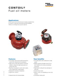
7 All was found in poor condition. Page 10 of 16 Finally the cargo hold bilge level alarm system was tested after renewal and found in satisfactory condition. Ch engineer and second engineer was satisfied with the system. DD) fuel Oil Flow meters As requested by supt to remove and bring out the fuel oil flow meters for shore calibration on URGENT basis. Therefore the following flow meters were remove and brought back to shore. The removed pipes was blanked with flanges as requested and for safety reason. - M/E fuel Oil Flow Meter 01 unit Make: NITTO Serial no: 0166978 - G/E fuel Oil Flow Meter 01 unit Make: NITTO Serial no: 0166979 - contoil Flow Meter 01 unit Serial no: 4668294 Picture below indicating the removal of flow meters locate inside purifier room Page 11 of 16 The 3 no s flow meters was calibrated and obtained meter factor accordingly.
8 Finally the flow meters was delivered on board and installed. After running for 1 day during vessel shifting to anchorage, second engineer complained that the G/E fuel oil flow meter was not working. Therefore, when we attended the vessel at anchorage, we opened up dismantled the counter assembly to investigate the fault. The counter assembly was removed from the flow meter to investigate on the fault complained. We then dismantle the magnetic gear shaft and found it was jammed due to some small particle found stuck inside. So we dismantle the complete piece, serviced and assemble back to original. Then installed back and tested to satisfactory. Ch engineer and 2nd engineer was satisfied. Finally all the flow meters was tested and found in satisfactory and ready for operation. Page 12 of 16 EE) Installation of New fuel Oil Leakage Alarm system As discuss with supt.
9 On board the vessel, we are requested to design, supply and install a new fuel oil leakage alarm system on the existing fuel oil leakage line located in the engine room platform. So we discussed, sketch a drawing and agreed by supt that we will design according to drawing. Upon confirmation, we start the fabrication of new oil tank with one inlet on top, one outlet return line, one testing oil inlet on top of the tank and a horizontal float installed to the tank. Picture below indicating the newly fabricated oil tank. Testing with oil inlet Oil leakage inlet Outlet return line We also installed a valve on the inlet line to oil tank and outlet return line as requested by ch engineer. So as requested by supt. we start to remove the main fuel oil leakage pipe which was about 350mm diameter, and transport to the engine room workshop where the hot works can take place.
10 See Picture below Page 13 of 16 After dismantling the big pipe and lifting it down, we transported the pipe to the engine room workshop. There, the ship crew assisted us in the hot works. We cut the socket out and welded a 2 inch pipe elbow pipe with a flange connection. Page 14 of 16 After hot works completed, we transport back the big pipe to its original location and fit in place so that we can start to fabricate the 2 inch pipe from the flange connection to the new oil tank. Newly fabricated 2 inch pipe new oil tank After all pipe fabrication, we installed the magnetic float switch and connected the cable which we had run from engine Control room console to the engine room bottom platform at the newly oil tank. Magnetic float switch Page 15 of 16 We also fabricated a new alarm panel with two alarm points (one as spare).
