Transcription of PID TEMPERATURE CONTROLLERS - RS Components
1 3200 PID TEMPERATURECONTROLLERSUser GuideENGA pplicato ai modelli 3216,3208 e 3204 ITASPAR eguladores PID deTemperatura Serie 3200 PIDThis booklet includes:English language - HA028582 Italian language - HA028582 ITA Iss. 1 Spanish language - HA028582 SPA Iss. 1 1 3200 Series PID TEMPERATURE CONTROLLERS Applies to Model numbers 3216, 3208 and 3204 Part number HA028582. Issue , Aug-04. Applies to software version 2 2 Contents 1. What Instrument Do I Have? .. 4 Unpacking Your controller ..4 Step 1: Installation ..6 Panel Mounting the controller ..6 Panel Cut-out Sizes ..6 Recommended minimum spacing of CONTROLLERS . Applies to all Model To Remove the controller from its Ordering 2.
2 Step 2: Wiring .. 9 Terminal Layout 3216 Terminal Layout 3208 and 3204 CONTROLLERS ..10 Wire Sizes ..11 Sensor Input (Measuring Input) ..11 Input/Output 1 & Output 2 ..12 Output Output 4 (AA Relay) ..13 Digital Inputs A & Current Transformer ..15 Transmitter Power Digital Communications ..16 controller Power Supply ..17 Example Wiring 3 3. Safety and EMC Installation Safety 19 4. Switch Initial Configuration .. 23 To Re-Enter Quick Code configuration mode .. 26 Pre-Configured controller or Subsequent Starts .. 26 Front panel layout .. 27 To Set The Target TEMPERATURE (setpoint).. 28 Alarm Indication .. 28 Auto, Manual and Off 28 To Select Auto, Manual or OFF Mode .. 29 Operator Parameters in Level 1.
3 30 5. Operator Level 2 ..31 To Enter Level 2 .. 31 To Return to Level 1 ..31 Level 2 Parameters ..31 Timer Operation .. 40 Dwell Timer .. 41 Delayed Timer .. 42 Soft Start Timer .. 43 44 Programmer Servo Mode and Power 45 To Operate the Programmer .. 46 To Configure the Programmer .. 47 4 Installation and Basic Operation 1. What Instrument Do I Have? Thank you for choosing this 3200 series TEMPERATURE controller /Programmer. The 3200 series provide precise TEMPERATURE control of industrial processes and is available in three standard DIN sizes:- 1/16 DIN Model Number 3216 1/8 DIN Model Number 3208 1/4 DIN Model Number 3204 A universal input accepts various thermocouples, RTDs or process inputs.
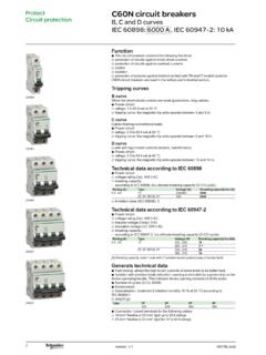
4 Up to three (3216) or four (3208 and 3204) outputs can be configured for control, alarm or re-transmission purposes. Digital communications and a current transformer input are available as options. The controller may have been ordered to a hardware code only or pre-configured using an optional Quick Start code. The label fitted to the side of the sleeve shows the ordering code that the controller was supplied to. The last two sets of five digits show the Quick Code. If the Quick Code shows **/** the controller will need to be configured when it is first switched on. This User Guide takes you through step by step instructions to help you to install, wire, configure and use the controller . For features not covered in this User Guide, a detailed Engineering Manual, Part No HA027986, and other related handbooks can be downloaded from Unpacking Your controller The following items are included in the box: controller mounted in its sleeve Two panel retaining clips AN IP65 sealing gasket mounted on the sleeve Component packet containing a snubber for each relay output and a resistor for current inputs (see section 2) This User Guide 5 Dimensions General views of the CONTROLLERS are shown below together with overall dimensions.
5 Label showing Order Code Serial Number including date of manufacture Latching ears Panel retaining clipsLatching ears 48mm ( ) IP65 Sealing Gasket 48mm ( ) 90mm ( )96mm ( ) 48mm ( ) 96mm ( )90mm ( ) ( ) Panel retaining clipTop View - Model 3216 Side View Model 3216 Model 3204 Model 3208 Models 3208 and 3204 Model 3216 6 Step 1: Installation This controller is intended for permanent installation, for indoor use only, and enclosed in an electrical panel Select a location which is subject to minimum vibrations, the ambient TEMPERATURE is within 0 and 55oC (32 - 131oF) and humidity 5 to 95% RH non condensing. The controller can be mounted on a panel up to 15mm thick To ensure IP65 and NEMA 4 front sealing against dust and water, mount on a non-textured surface.
6 Please read the safety information in section 3 before proceeding. The EMC Booklet part number HA025464 gives further installation information. Panel Mounting the controller 1. Prepare a cut-out in the mounting panel to the size shown. If a number of CONTROLLERS are to be mounted in the same panel observe the minimum spacing shown. 2. Fit the IP65 sealing gasket behind the front bezel of the controller 3. Insert the controller through the cut-out 4. Spring the panel retaining clips into place. Secure the controller in position by holding it level and pushing both retaining clips forward. 5. Peel off the protective cover from the display Panel Cut-out Sizes . 45 mm - + inch , + 92 mm - + inch , + 45 mm - + inch , + Model 3216 Model 3208 Model 3204 92 mm - + inch , + 92 mm - + inch , + 7 Recommended minimum spacing of CONTROLLERS .
7 Applies to all Model sizes 1 To Remove the controller from its Sleeve The controller can be unplugged from its sleeve by easing the latching ears outwards and pulling it forward out of the sleeve. When plugging it back into its sleeve, ensure that the latching ears click back into place to maintain the IP65 sealing. 10mm ( inch)38mm ( inch)(Not to scale) 8 Ordering Code 1 2 3 4 5 6 7 8 9 10 11 12 13 8/9 Product/Manual Language English ENG French FRA German GER Italian ITA Spanish SPA Quick Start Code See Section 4 7.
8 Fascia colour Green G Silver S 4. Outputs 1, 2 and 3 3216 3208 and 3204 OP1 OP2 OP1 OP2 OP3 L R L R R R R R R R L L L L R L D L R D D R R R D D D D D D L X X X Where: L=Logic (SSR drive), R = Relay, D = DC 6.
9 Options Not fitted XXX RS485 & Digital input A 4XL RS232 & Digital input A 2XL RS485, CT & Dig in A 4CL RS232, CT & Dig in A 2CL Digital input A XXL CT & Digital input A XCL 10. Extended Warranty Standard XXXXX 3 year WL003 5 year WL005 11. Certificates None XXXXX Conformity CERT1 Factory Cal CERT2 UKCAS CERT3 12. Custom Label FXXXX 13. Specials Number XXXXXX 3. Power Supply 20 29V VL 100 240V VH 2. Function controller CC Programmer CP 5. AA Relay (OP4) Not fitted X Relay (Form C) R 1. Model 1/16 DIN Size 3216 1/8 DIN Size 3208 1/4 DIN Size 3204 9 2.
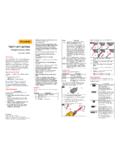
10 Step 2: Wiring Terminal Layout 3216 controller Warning Ensure that you have the correct supply for your controller Check order code of the controller supplied Key to symbols Logic (SSR drive) output mA analogue output Relay COMA(+) B(-) Digital Communications RS232 RS485 AA relay (OP4) AAABACVIV+V-1A1B2A2BL N CT C LA HD HE HF - + T/CmV + - Sensor Input Pt100 mA - + + + - - + + - - Line Supply 100 to 240 Vac 50/60Hz OR Low Voltage Supply 24 Vac/dc Input/Output 1 Output 2CT input & Digital input A 10 Terminal Layout 3208 and 3204 CONTROLLERS Warning Ensure that you have the correct supply for your controller Check order code of the controller supplied Key to symbols Logic (SSR drive) output mA analogue output Relay Digital Communications RS232 or RS485 AA Relay (OP4)